Do you have a question about the Benchmark Scientific Bioclave and is the answer not in the manual?
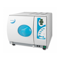
Description of the sterilizer's purpose, compliance with directives, and ASME certification.
Detailed technical specifications including chamber size, voltage, power, temperature, and dimensions.
List of items included in the sterilizer package, such as the unit, trays, and manuals.
Guidelines for proper installation, including required ventilation space and placement.
Initial setup steps including unpacking, connecting power, and powering on the unit.
Instructions for filling the distilled water tank, including a warning for overfilling.
Guidelines for arranging samples on trays and using sterilization paper for effective sterilization.
Explains how to use the LCD panel, temperature, and program buttons to select a cycle.
Procedures for placing materials in the chamber and closing the door to start a sterilization cycle.
Details on initiating the sterilization cycle and its estimated duration.
Explains what happens upon cycle completion, including printer output and door unlocking.
Steps to enter the advanced settings mode by holding the START button during power-on.
Options available in S1 state, including changing temperature/pressure units and adjusting time/date.
Features in S2 state, such as checking cycle count and setting high altitude parameters.
Adjusting sterilization and drying times, holding time, and parameters for S3 state.
Instructions for connecting the optional printer, including cable and power.
How to use a USB drive to store cycle reports and file naming conventions.
Steps to access and print/save previous cycle information using the PROGRAM and TEMP buttons.
Weekly cleaning procedure for the distilled water tank using isopropyl alcohol or disinfectant.
Weekly cleaning of the sterilization chamber and trays using a damp cloth.
Weekly cleaning of the door seal with a smooth cloth and distilled water.
How to adjust the door seal using the provided tool to prevent steam leaks.
Step-by-step guide for removing and installing a new door seal ring.
Instructions on how to operate the drain valve to drain the water tank.
Lists common error codes, their descriptions, and proposed solutions for troubleshooting.
Details the various safety devices incorporated into the sterilizer for protection.
Details the required properties and characteristics for feed water and condensate.
Provides a table summarizing sterilization programs, temperature, pressure, and load capacity.
Illustrates the electrical connections and components of the sterilizer.
Shows the hydraulic system layout, including valves, pump, and tanks.
| Brand | Benchmark Scientific |
|---|---|
| Model | Bioclave |
| Category | Laboratory Equipment |
| Language | English |