LifeGuard® Series
LG_D00393_00_Q_XXEN / 05.2019 7
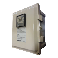
Digital Display Option
Wiring - Control and Remote Indicator Wiring (Backplate Only)
This section applies to LifeGuard model numbers ending in “-N-D”. Follow the standard wir-
ing instructions shown above. Additionally, backplate-only models can be connected to ad-
ditional devices for remote capabilities. Enclosed models have the digital display prein-
stalled with no additional wiring required.
Test and reset functions are carried out in one of the following ways:
• Using the test and reset pushbuttons located directly on the RCMA-series ground fault
module.
• Connecting an optional MK1500-D remote indicator and using he built-in test and reset
buttons.
• Connecting an optional MK1500-D remote indicator and using t´s TEST, RESET, and T/R
terminals to connect external test and reset pushbuttons as shown in the drawing below.
The optional MK1500-D duplicates RCMA-module indication and test/reset pushbutton
functionality. Additionally, terminals are provided for external test and reset. Both are con-
figured for normally open (N.O.) contacts.
Observe the following additional requirements:
• Use shielded RS-485 cable, AWG 18 for connections “A” and “B.”
• The red switch labeled “R” on the underside of the ground fault module must be
switched to ON to ensure proper RS-485 termination. Standard RS-485 cable length lim-
itations apply.
• External test and reset control connections are optional and not necessary for the built-in
test and reset functionality of the MK1500-D and ground fault module.
• The MK1500-D requires an external supply voltage not supplied from the backplate, con-
nected to terminals A1 and A2. The supply voltage range is 100-240 VAC, 50/60 Hz.
Refer to the wiring diagram below. For additional information on installation and use of the
remote indicator, refer to MK1500-D installation manual.
MK1500
POWER
ON
CIRCUIT
TRIPPED
I mAI mA
%
25 50 75 100
TEST RESET
MK1500-D
i
Do not modify any other wiring on the
backplate when installing the remote.
 Loading...