3
TBP401003deen / 09.2008
RCM470LY / RCM475LY
– Führen Sie die zu überwachenden Leiter durch den
Messstromwandler. Beachten Sie die Hinweise im Bei-
packzettel des Messstromwandlers.
Anschluss zum Messstromwandler:
Siehe Technische Daten „Leitungslängen für Messstrom-
wandler“.
RCM475LY-.. :
– Führen Sie die zu überwachenden Leiter durch den ein-
gebauten Messstromwandler.
3. Anschluss an das Alarm-Relais
Schließen Sie Komponenten, die bei auftretenden Alar-
men geschaltet werden sollen, an die Ausgangsklemmen
des Alarm-Relais an. Beachten Sie die von dem Relais maxi-
mal schaltbaren Spannungen und Ströme (siehe Typen-
schild).
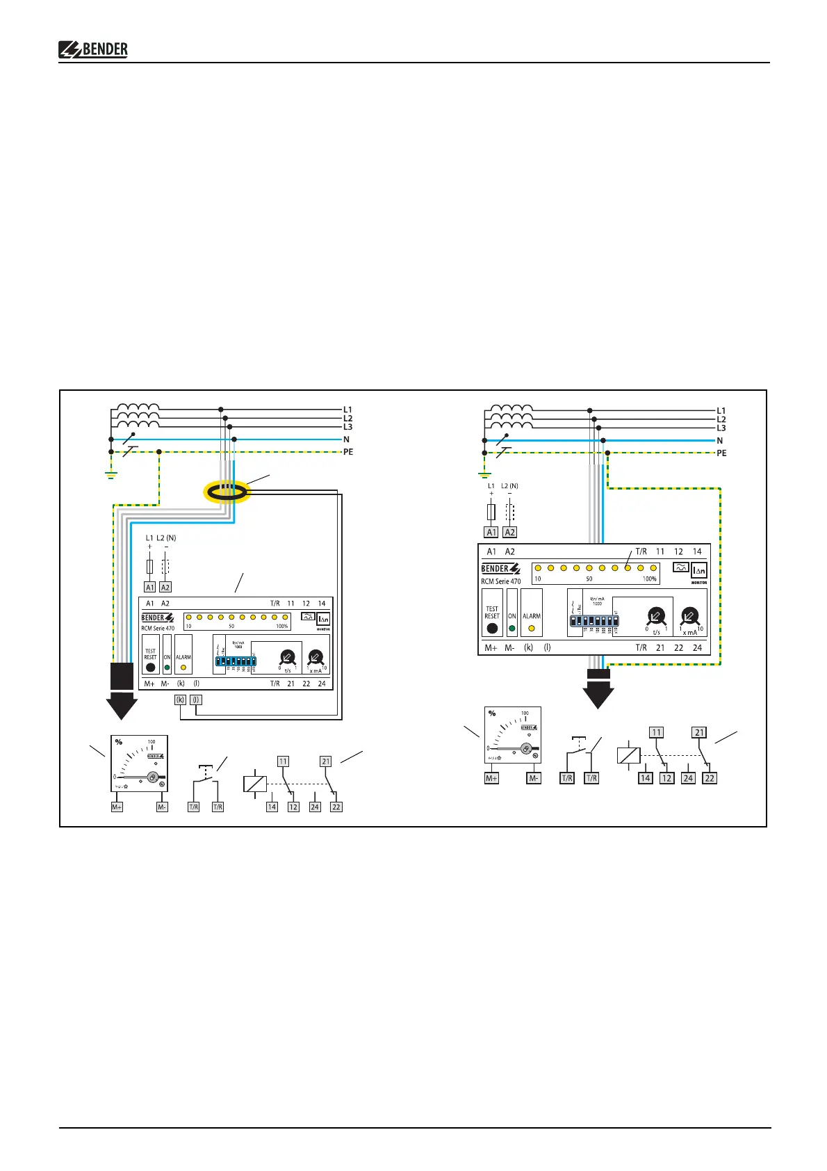
Anschlussschaltbild
Legende zum Anschlussschaltbild
1 Differenzstrom-Überwachungsgerät RCM470LY-..
2 Externer Messstromwandler für RCM470LY-.. Siehe Tabel-
le „Externe Messstromwandler“
Achtung: PE nicht durch den Messstromwandler führen!
3 Differenzstrom-Überwachungsgerät RCM475LY-..
4 Externes Anzeigeinstrument
5 Externe Taste "TEST / RESET"
6 Alarmrelais:
... schaltet im Alarmfall. Ein Alarm erfolgt bei Erreichen des
Ansprechwertes und nach Ablauf der Ansprechzeitverzö-
gerung. Das RCM470LY meldet auch bei Unterbrechung
des externen Messstromwandlers einen Alarm.
A1, A2 Versorgungsspannung siehe Typenschild
F Kurzschlussschutz Versorgungsspannung U
s
,
Empfehlung: 6 A Sicherung
k, l Nur RCM470LY: Anschluss Messstromwandler
1
2
F
F
6
5
4
Observe the instructions in the CT instruction leaflet.
CT connection:
Refer to the technical data „Cable lengths for measuring
current transformers“.
RCM475LY-.. :
– Lead the conductor to be monitored through the inter-
nal measuring current transformer.
3. Connection to the alarm relay:
Connect the devices to be activated in the event of an
alarm to the output terminals of the alarm relay. Refer to
the nameplate for the maximum voltages and currents the
relay is able to switch.
Wiring diagram
Legend to wiring diagram
1 Residual current monitor RCM470LY-..
2 External CT for RCM470LY-.. See table „External CTs“; At-
tention: The PE conductor must not be passed through
the measuring current transformer!
3 Residual current monitor RCM475LY-..
4 External indicating instrument
5 External test and reset button
6Alarm relay:
... trips in case of alarm. An alarm occurs when the re-
sponse value is exceeded and after the response delay
time has expired. The RCM470LY also issues an alarm in
case of measuring current transformer interruption.
A1, A2 Supply voltage see name plate
F Short-circuit protection supply voltage U
s
,
6 A fuse recommended
k, l RCM470LY only: Connection measuring current transformer
3
6
5
4