5
BENDIX
®
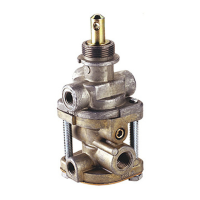
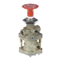
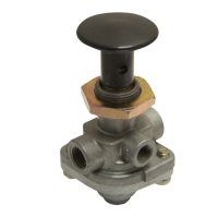
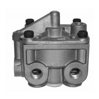
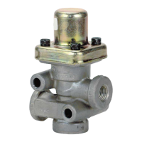
PP-1
®
, PP-8
™
, & RD-3
™
VALVES
1. Run the vehicle until the air system reaches full
reservoir pressure (120‑135 psi). Turn o the vehicle.
2. Move the control valve button & plunger from side to
side and up and down. Do not push the button in. If
there is any play, or if audible leakage is detected, the
valve must be replaced.
3. Identify the dash valve exhaust hose location – if there
is a hose still connected to the Park Control Valve
Exhaust Port, it is advised to disconnect it and remove
any tting.
4. With the button pulled out (exhaust position), rotate the
button and plunger in a clockwise direction – stopping
every 90º to check for leakage.
5. Using a soap solution, check for leaks. The allowable
leakage should not exceed a 1” bubble in 5 seconds
at any location on the valve.
6. Push the button in (applied position) and check for
leaks. (The Bendix
®
RD-3
™
valve will have to be
manually held in this position.) The leakage should
not exceed a 1” bubble in 3 seconds at any location
on the valve.
7. Reduce the supply pressure. At a pressure from 60
to 20 psi, depending on the part number specic
automatic release pressure, the button should pop out
automatically, exhausting the delivery volume. (This
does not apply to the RD-3, PP-8 or some PP-1 valves
without an automatic release pressure).
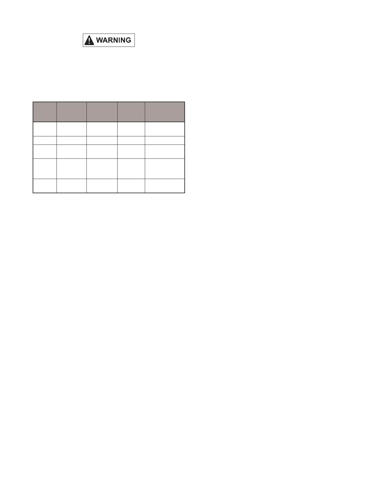
OPERATING AND LEAKAGE TESTS
Do not install ttings or tubing into the exhaust port
if used for parking brake control. If a worn PP-1 or
PP-8 valve is used for parking brake control and the
exhaust plumbing is kinked, bent, or restricted, the
vehicle might not park, and a roll away may result,
potentially resulting in injury or death.
Bendix
®
Valve
Automatic
Exhaust
(psi)
Momentary
Apply
Pilot Trip
Feature
(psi)
Non-Automatic
PP-1
®
20, 30, 40
or 60
– – –
PP-2
™
40 – – –
PP-5
™
40, 50
or 60
– 18 or 24 –
RD-3
™
–
Must
be held
manually
– –
PP-8
™
– – –
Will remain in
either position
Table 1 - Push-Pull Type Control Valves Operation
BENDIX
®
PP-5
™
VALVE
1. Proceed as for Bendix
®
PP-1
®
valve through Step 4.
2. Connect a modulated source of air pressure to the pilot
air inlet. With the button pushed in (applied position)
with 125 psi supply pressure and a gradually increasing
pressure applied at the pilot air port, the valve should
move to the release position with a pilot pressure of
not more than 18 psi. Leakage in this mode should not
exceed a 1-in. bubble in three (3) seconds at the
exhaust port and a 1‑in. bubble in ve (5) seconds at
the plunger stem.
BENDIX
®
PP-2
™
VALVE
1. Proceed as for the PP-1 valve through Step 1.
2. With the button pulled out (exhaust position), leakage
at the brake valve port or at the plunger stem should
not exceed a 1‑in. bubble in ve (5) seconds.
3. Push the button in. Supply pressure should be present
in the delivery volume. Leakage at the exhaust port
or around the plunger stem should not exceed a 1-in.
bubble in ve (5) seconds.
4. Pull the button out and apply supply pressure at the
brake valve port. Supply pressure should be present
in the delivery volume and leakage at the exhaust port
should not exceed a 1‑in. bubble in ve (5) seconds.
NOTE: If any of the above push-pull valves do not
function as described or if leakage is excessive,
it is recommended they be returned to our
nearest authorized distributor for a service new or
remanufactured replacement.