EasyManua.ls Logo

BENDIX TABS-6 TRAILER ABS MODULE User Manual

BENDIX TABS-6 TRAILER ABS MODULE
32 pages
To Next Page IconTo Next Page
Page #1 background imageLoading...
Page #1 background image
1
Bendix
®
TABS-6 Trailer ABS Module
FIGURE 1 - TABS-6 STAndARd And PREmIUm mOdULES
INTRODUCTION
The Bendix
®
TABS-6 module is an integrated trailer ABS
controller and modulator for air-braked heavy-duty trailers,
semi-trailers and dollies. The module acts as a relay valve
during normal braking, but during ABS events, it will intervene
to help improve stability. All modules include an Electronic
Control Unit (ECU) and Modulator Relay Valve (MRV) which are
integrated into a single self-contained 2S/1M (two-sensor, one
modulator) trailer ABS unit. The Premium TABS-6 module is
auto-congurable to control more sensors and modulators (up to
4S/3M) from its default 2S/1M.
Bendix
®
TABS-6 modules also feature:
Internal electrical connections to the primary MRV,
eliminating the need for external pigtail harnesses.
Optional mounting to the service reservoir or to the chassis,
without additional brackets.
Blink code diagnostics and support for advanced diagnostic
tools.
Support for Power Line Carrier (PLC) communication to the
towing vehicle.
A pressure equalizing valve in the sealed ECU housing to
give improved protection from water, etc.
A locking dust cover to provide additional electrical connector
and cable protection.
A serviceable nylon lter to help prevent foreign material
from entering the control port.
TABLE OF CONTENTS PAGE
General System Information
Introduction . . . . . . . . . . . . . . . . . . . . . . . . . . . . . . . .1
Safe Maintenance Practices . . . . . . . . . . . . . . . . . . . 2
Components . . . . . . . . . . . . . . . . . . . . . . . . . . . . . . .2
Mounting Congurations. . . . . . . . . . . . . . . . . . . . . . 2
PLC Communications . . . . . . . . . . . . . . . . . . . . . . . . 2
Wiring Harness (Pigtail) . . . . . . . . . . . . . . . . . . . . . . 3
Power and Ground . . . . . . . . . . . . . . . . . . . . . . . . . .4
ABS Indicator Lamp . . . . . . . . . . . . . . . . . . . . . . . . . 4
Wheel Speed Sensors . . . . . . . . . . . . . . . . . . . . . . . 5
BR9235
ABS Modulator Valve . . . . . . . . . . . . . . . .5
J1708/J1587 Diagnostic Link . . . . . . . . . . . . . . . . . . 6
Auxiliary I/O . . . . . . . . . . . . . . . . . . . . . . . . . . . . . . .6
ABS Flex
Program . . . . . . . . . . . . . . . . . . . . . . . . .6
Customer Scratch Pad . . . . . . . . . . . . . . . . . . . . . . .6
Power-up Sequence . . . . . . . . . . . . . . . . . . . . . . . . . 6
ABS Operation . . . . . . . . . . . . . . . . . . . . . . . . . . . . . 7
Auto-Conguration . . . . . . . . . . . . . . . . . . . . . . . . . . 8
Odometer Function . . . . . . . . . . . . . . . . . . . . . . . . . . 8
Non-standard Tire Size . . . . . . . . . . . . . . . . . . . . . . . 8
Diagnostic Trouble Code Detection . . . . . . . . . . . . . 8
Blink Code Diagnostics. . . . . . . . . . . . . . . . . . . . . . . 9
Bendix ABS Diagnostic Tools . . . . . . . . . . . . . . . . . 13
Contacting Bendix. . . . . . . . . . . . . . . . . . . . . . . . . .14
Servicing the Module . . . . . . . . . . . . . . . . . . . . . . . 14
Removing the Module. . . . . . . . . . . . . . . . . . . . . . . 14
Service Replacement using the Module . . . . . . . . . 15
Reinstallation . . . . . . . . . . . . . . . . . . . . . . . . . . . . . 15
Leakage And Operational Tests . . . . . . . . . . . . . . .15
ABS Wiring . . . . . . . . . . . . . . . . . . . . . . . . . . . . . . .16
Troubleshooting . . . . . . . . . . . . . . . . . . . . . . . . 17-27
3/4" NPT
Supply Port
Through-holes
for Frame
(Chassis)
Mounting
Wheel Speed
Sensor
Connectors
ECU Pin-out Label
(See Page 31)
ECU Cover
(Sealed)
ECU Connector
Cover
(Removable)
Four (4) 3/8" NPT
Delivery Ports
(To Brake Chambers)
3/8" NPT Control
Port with
Integral Filter
The ECU Connector
Varies for Standard and
Premium - See Chart
Integrated
Modulator
Relay Valve
Part Number
Label
(See Page 31)
To Remove Cover
Slide Lock Tab
The Premium TABS‑6
Module uses an
18‑Pin Connector
The Standard TABS‑6
Module uses a
5‑Pin Connector
SD-13-4767
Question and Answer IconNeed help?

Do you have a question about the BENDIX TABS-6 TRAILER ABS MODULE and is the answer not in the manual?

BENDIX TABS-6 TRAILER ABS MODULE Specifications

General IconGeneral
ModelTABS-6
TypeTrailer ABS Module
Input Voltage12/24V DC
Operating Voltage9V to 32V
Operating Temperature Range-40°C to +85°C
Communication ProtocolSAE J1939
CompatibilityCompatible with various trailer types
Number of Wheel Speed SensorsUp to 4

Summary

INTRODUCTION

SAFE MAINTENANCE PRACTICES

COMPONENTS

MOUNTING CONFIGURATIONS

Tank (Nipple) Mount

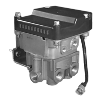
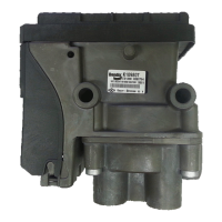
Describes mounting the TABS-6 module to a trailer supply tank via a 3/4" NPT nipple.

Frame (Chassis) Mount

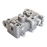
Details frame mounting using through-holes and specific bolt torque specifications.

POWER LINE CARRIER (PLC) COMMUNICATIONS

Identifying and Measuring the PLC Signal

Explains how to identify and measure the PLC signal using oscilloscopes or diagnostic tools.

PIGTAIL WIRING HARNESSES

ECU Connectors

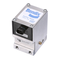
Describes the 5-pin Packard Weather Pack and 18-pin Deutsch DT ECU connectors for standard and premium modules.

ABS INDICATOR LAMP

Trailer-mounted Lamp

Explains the function and connection of the trailer-mounted ABS indicator lamp.

Dash-mounted Lamp (PLC Controlled)

Details how the dash-mounted indicator lamp is controlled via PLC communication.

BENDIX® WS-24™ WHEEL SPEED SENSORS

BENDIX® BR9235™ ABS MODULATOR RELAY VALVES

J1708/J1587 DIAGNOSTIC LINK

ABS FLEX™ PROGRAM

POWER-UP SEQUENCE

ABS OPERATION

Axle Control

Details how the system controls wheels on both sides of an axle for ABS events.

Dolly-Axle Control (Select Low)

Explains Dolly-Axle control for unbalanced braking surfaces to maintain stability.

Side Control

Describes how the system controls wheels on each side individually for stability.

AUTO-CONFIGURATION

ODOMETER FUNCTION

Odometer

Describes the module's built-in odometer function for accumulating vehicle mileage.

Trip Counter

Details the trip counter feature accessed via diagnostic tools for recording trip mileage.

NON-STANDARD TIRE SIZE

DIAGNOSTIC TROUBLE CODE DETECTION

PARTIAL ABS SHUTDOWN

ECU Diagnostic Trouble Codes

Explains that all ABS functions are disabled and the system reverts to normal braking.

Voltage Diagnostic Trouble Code

Describes how out-of-range voltage disables ABS functionality, reverting to normal braking.

BLINK CODE DIAGNOSTICS

Display Active Diagnostic Trouble Codes

Outlines the procedure to display active fault codes using blink codes and brake pedal input.

Display Diagnostic Trouble Code History

Details how to retrieve past fault codes using blink code sequences and brake pedal presses.

Reset Active Diagnostic Trouble Codes

Explains how to clear active fault codes using blink code diagnostics and brake pedal interaction.

Diagnostic Trouble Codes (DTCs)

Display Configuration

Describes how to check the current ABS configuration using blink codes and brake pedal inputs.

Display Odometer Mileage

Explains how to view the trailer odometer mileage via blink code displays.

Resetting ABS Configuration

Details the process to reset the ABS configuration to the default 2S/1M using blink codes.

POWER

Lists diagnostic trouble codes related to power supply issues like over-voltage or low-voltage.

MODULATOR (MOD)

Covers DTCs related to modulator hold/release solenoids, dynamic errors, and configuration.

COMMON

Includes common DTCs for modulator switches, dynamic errors, and excessive ABS activity.

ELECTRONIC CONTROL UNIT (ECU)

Details DTCs related to internal ECU errors and ECU configuration issues.

J1587 DIAGNOSTIC

Describes DTCs for J1587 diagnostic link issues, including wiring and connector checks.

TRAILER-MOUNTED ABS INDICATOR LAMP

Details DTCs related to the trailer-mounted ABS indicator lamp, including shorts or open circuits.

Troubleshooting: Using Hand-Held or PC-Based Diagnostic Tools

BENDIX ABS DIAGNOSTIC TOOLS

Introduces Bendix diagnostic tools like ACom software and the TRDU tool for system support.

Bendix® TRDU™ Tool Reset Function

Details the magnetic reset function for the TRDU tool to clear DTCs or reset ABS configuration.

MPSI Bendix Cartridge

Describes the MPSI cartridge for use with Pro-Link diagnostic tools for Bendix systems.

PLC Diagnostic Tool

Information on diagnostic tools for detecting and analyzing PLC signals on the power line.

CONTACTING BENDIX

Provides information on how to contact Bendix for support, troubleshooting guides, and contact directories.

SERVICING THE TABS-6 MODULE

REMOVING THE TABS-6 MODULE

Provides step-by-step instructions for safely removing the TABS-6 module from the vehicle.

SERVICE REPLACEMENT OF OTHER ABS CONTROLLERS

Details how the TABS-6 module replaces older Bendix ABS controllers like MC-12, MC-30, A-18.

REINSTALLATION OF THE TABS-6 MODULE

Outlines the procedure for correctly reinstalling the TABS-6 module after service or replacement.

LEAKAGE AND OPERATIONAL TESTS

ABS WIRING

Troubleshooting: Electrical Schematics

Troubleshooting: System Schematics

2S/1M - AXLE CONTROL

Shows the system schematic for a 2S/1M axle control configuration of the TABS-6 module.

2S/1M - DOLLY AXLE CONTROL

Illustrates the system schematic for a 2S/1M dolly axle control configuration.

2S/2M - AXLE CONTROL

Depicts the system schematic for a 2S/2M axle control configuration, detailing component connections.

2S/2M - SIDE CONTROL

Presents the system schematic for a 2S/2M side control configuration, showing component layout.

4S/2M - AXLE CONTROL

Illustrates the system schematic for a 4S/2M axle control configuration, including sensor and modulator connections.

4S/2M - SIDE CONTROL

Shows the system schematic for a 4S/2M side control configuration, highlighting component interconnections.

4S/3M - SIDE/AXLE CONTROL

Displays the system schematic for a 4S/3M side/axle control configuration, detailing component placement.

Troubleshooting Flowcharts

Section A: Trailer-Mounted ABS Indicator Lamp

Flowchart for troubleshooting the trailer-mounted ABS indicator lamp during power-up.

Section B: Dash-Mounted ABS Indicator Lamp

Flowchart for diagnosing dash-mounted ABS indicator lamp issues at power-up.

Section C: Blink Code Quick Reference

Quick reference for diagnostic trouble codes using blink code sequences and brake pedal input.

Section D: TRDU™ Tool LED Quick Reference

Quick reference for interpreting DTCs using the TRDU tool's LED indicators for Bendix ABS systems.

Section E: Troubleshooting the Trailer-Mounted ABS Indicator Lamp Circuitry

Detailed steps for troubleshooting the trailer-mounted ABS indicator lamp circuit.

Section F: Troubleshooting the Power Supply

Guides on troubleshooting power supply issues for the TABS-6 module, including voltage checks.

Section G: Troubleshooting the WS-24™ Wheel Speed Sensors

Outlines troubleshooting for WS-24™ wheel speed sensors, covering static and dynamic DTCs and checks.

Section H: Troubleshooting the Modulator Relay Valves

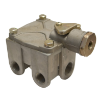
Provides troubleshooting steps for modulator relay valves, including static and dynamic DTCs and checks.

ECU Part Number Label

Related product manuals