EasyManua.ls Logo

BENDIX MV-3 DASH CONTROL MODULE User Manual

BENDIX MV-3 DASH CONTROL MODULE
6 pages
To Next Page IconTo Next Page
Page #1 background imageLoading...
Page #1 background image
1
®
SD-03-3415
DESCRIPTION
The Bendix
®
MV-3
dash control module is a two-button,
push-pull control valve housed in a single body which includes
a dual circuit supply valve and a check valve. The MV-3
valve can duplicate the functions of any existing two or three
valve push-pull system and has the advantages of reduced
plumbing.
The MV-3
valve body, plungers and spools are made out of
a non-metallic, non-corrosive material. All air connections
are at the back of the valve with the exception of the optional
auxiliary port as shown in Figure 1.
The MV-3
valve provides the following functions:
1 - Tractor Protection.
2 - Trailer Service Air Control.
3 - System Park.
4 - Trailer Park Only.
5 - Trailer Charge with Tractor Spring Brakes Applied (Tractor
Park Only).
6 - Supply Reservoir Selection.
7 - Primary & Secondary Reservoir Connections.
FIGURE 2 - MV-3
DASH CONTROL MODULE AIR
CONNECTIONS
DELIVERY
DELIVERY
SUPPLY
#1
EXHAUST
PORT
AUXILIARY
DELIVERY
PORT
TRAILER
SUPPLY
LINE
TRACTOR
SPRING
BRAKES
SUPPLY
#2
TRACTOR
SERVICE
RESERVOIR #2
TRACTOR
PROTECTION
VALVE
TRACTOR SERVICE
RESERVOIR #1
Bendix
®
MV-3
Dash Control Module
FIGURE 1 - MV-3
DASH CONTROL MODULE
TRACTOR
DELIVERY
DUAL CIRCUIT
SUPPLY
VALVE
SECONDARY
SUPPLY
EXHAUST
BOTTOM VIEW
TRAILER
DELIVERY
SECONDARY
SUPPLY
TRACTOR
DELIVERY
MOUNTING
HOLES
(4)
TRAILER
DELIVERY
AUXILIARY
PORT
(OPTIONAL)
MOUNTING
PLATE
PRIMARY
SUPPLY
Question and Answer IconNeed help?

Do you have a question about the BENDIX MV-3 DASH CONTROL MODULE and is the answer not in the manual?

BENDIX MV-3 DASH CONTROL MODULE Specifications

General IconGeneral
BrandBENDIX
ModelMV-3 DASH CONTROL MODULE
CategoryControl Unit
LanguageEnglish

Summary

Bendix MV-3T Dash Control Module

Description

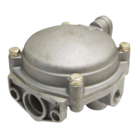
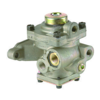
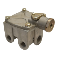
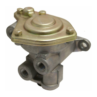
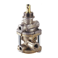
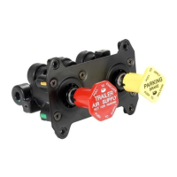
Explains the MV-3™ dash control module, its construction, and its functions.

Operation

Normal Operating Position

Details the system state when both buttons are pushed in, releasing all brakes.

Trailer Parking or Emergency Brake Actuation

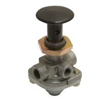
Describes how to apply trailer brakes by pulling the red button out.

System Operation Modes and Testing

System Park

How to actuate parking brakes on both tractor and trailer by pulling the yellow button out.

Trailer Charge

Recharging the trailer system while tractor spring brakes remain applied.

Automatic Application

How the trailer brakes automatically apply when supply pressure drops.

Operational Test

Procedures to verify the correct functionality of the MV-3™ valve.

General Safety Precautions

Essential safety instructions to avoid personal injury or death when working on the vehicle.

Maintenance and Assembly

Disassembly Procedure

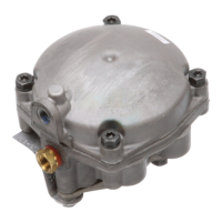
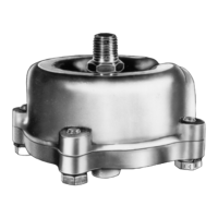
Detailed steps for disassembling the MV-3™ valve, including removing buttons, cover plate, spools, and check valve.

Cleaning and Inspection

Guidelines for cleaning non-metallic components and inspecting for damage.

Assembly Steps

Instructions for reassembling the MV-3™ valve, including dual circuit supply valve, spools, and final assembly.

Service Test

Final testing procedure after assembly and before returning the vehicle to service.

Related product manuals