6
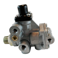
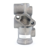
Tank (Nipple) Mounted
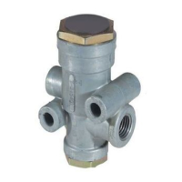
The BR9235
™
MRV can be tank-mounted using a schedule
80 (heavy gauge steel) 3/4" NPT nipple directly between
the trailer supply tank and the supply port. A tank with a
reinforced port must be used.
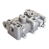
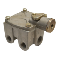
Bracket (Chassis) Mounted
The BR9235
™
MRV provides an option with a bracket
for frame mounting directly to the trailer frame rail or
crossmember. It is recommended to use two Grade 5,
3/8-16 bolts, torqued to 180 – 220 in-lbs.
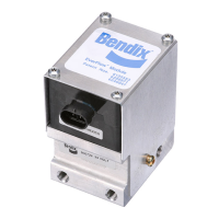
J1708/J1587 DIAGNOSTIC LINK
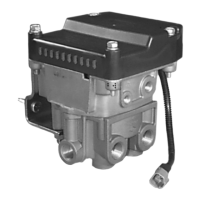
The Premium TABS-6 module provides a J1708/J1587
diagnostic link with data and power to communicate with
the vehicle and various diagnostic tools. Diagnostics,
testing, conguration, data transfer and other functions can
be performed using this link. Diagnostic tools such as the
MPSI Pro-Link
™
device and Bendix
®
ACOM
™
Diagnostic
Software (version 4.0 and higher) support the TABS-6
Module.
Ignition power must be provided to the TABS-6 module for
the diagnostic link to be active.
AUXILIARY I/O
The Standard module provides for one auxiliary I/O
function.
The Premium module provides for up to ve auxiliary
functions and one additional ground. See Chart 3, below.
Bendix
®
ACOM
™
Diagnostic Software (version 4.0 and
higher) supports the conguration of the TABS-6 module
auxiliary I/O’s.
ABS FLEX
™
PROGRAM
The ABS Flex
™
program uses Auxiliary Design Language
(ADL) to allow customized auxiliary functions to be carried
out by the TABS-6 module. Programs developed in the ABS
Flex
™
program may be downloaded at the production line or
in the eld to control non-braking functions of the trailer.
For example, ABS Flex
™
program can potentially
communicate the status of: tire ination and/or temperature;
reefer temperature; load presence; slider pin position;
lift axle position; proximity/reverse alarm; and vehicle
weight.
ABS Flex
™
programs monitor the auxiliary I/Os and/or the
SAE J1587 diagnostics and SAE J2497 PLC data links.
Contact your Bendix Account Manager to discuss an ABS
Flex
™
program for your vehicle(s).
CUSTOMER SCRATCH PAD
The TABS-6 module has a Customer Scratch Pad feature
which allows the customer, or end-user, to store up to 756
bytes of information. This information can then be read
using the Bendix
®
ACOM
™
Diagnostic Software (version
4.0 and higher).
If additional scratch pad space is needed, this storage
space can be expanded to 1K (1,008 bytes total of data).
Contact Bendix for further details.
POWER-UP SEQUENCE
At power-up, the TABS-6 module performs a series of self-
checks that can assist a technician to determine the ABS
system status and conguration.
Name ECU ECU Pin Auxiliary Functions Default Function
AUX Standard C None
AUX1 Premium 16 • High-Side Driver… or Digital Input Modulator 3 (MOD3)
Hold Solenoid
AUX2 Premium 10 • High-Side Driver… or Digital Input Modulator 3 (MOD3)
Release Solenoid
AUX3 Premium 15 • High-Side Driver… or Digital Input Modulator 2 (MOD2)
Hold Solenoid
AUX4 Premium 9 • High-Side Driver… or Digital Input Modulator 2 (MOD2)
Release Solenoid
AUX5 Premium 4 • Low-Side Driver… or Analog Input Modulator 3 (MOD3)
Common
AUX6 Premium 3 • High-Side Driver… or Digital Input J1587 Diagnostic Power
CHART 3 – AUxILIARY I/OS And dEFAULT FUnCTIOnS
• High-Side Driver… or Digital Input…
or • Analog Input