1
®
SD-13-4811
DESCRIPTION
The ATR-1
™
antilock traction relay is a specialized air brake
valve developed for use on Bendix antilock/traction equipped
vehicles.
It is essentially three separate valves working in combination
in a single housing. An R-14
™
style service relay is the base
valve and is fitted with a modified cover containing a double
check valve and a traction control solenoid. The ATR-1
™
valve
contains both air and electric components to provide the
service braking and traction control (differential braking)
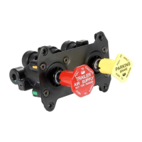
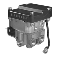
functions. A Bendix antilock traction controller can be
mounted to the ATR-1
™
valve or a cover plate can be installed
and the antilock controller mounted elsewhere on the vehicle.
When an ATR-1
™
valve is combined with an antilock traction
controller the resulting assembly is referred to as an antilock
traction assembly.
The ATR-1
™
valve replaces the standard relay valve used to
control the rear axle service brakes and performs the standard
relay function. Like the standard relay valve it replaces, the
ATR-1
™
valve (sometimes with attached antilock controller)
is normally mounted near the service brakes it serves. A
mounting bracket, furnished with the valve, permits either
frame or cross member mounting. All air connections on
the ATR-1
™
valve are identified for ease of installation. The
letter identification and air line connections are shown below
for reference.
EMBOSSED
ATR-1
™
VALVE AIR CONNECTION IDENT.
Supply (to reservoir) SUP
Delivery (to brake Chamber) DEL
Service (to brake valve rear delivery) SER
Control (not drilled or threaded on ATR-1
™
valve) CON
The ATR-1
™
valve is part of the R-12
™
family of relay valves
which includes the R-12
™
, R-14
™
, BP-R1
™
, AR-1
™
.
The internal components of the relay portion of all of these
valves are interchangeable with the R-12
™
valve and therefore
the same basic components are used to service all of them.
The ATR-1
™
valve is available with various crack pressures
to accommodate specific applications, however the standard
is 4 psi.
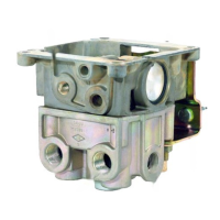
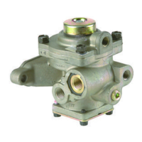
Bendix
®
ATR-1
™
AntiLock Traction Relay Valve
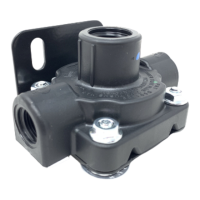
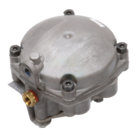
SUPPLY
PORT
BODY
MOUNTING
BRACKET
SERVICE
PORT
CONTROLLER
MOUNTING HOLES (4)
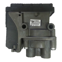
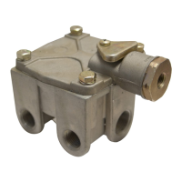
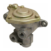
COVER PLATE FOR
REMOTE MOUNT
REMOTE MOUNT ATR-1
™
RELAY VALVE
TRACTION CONTROL
SOLENOID
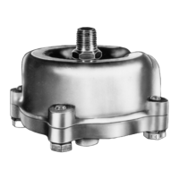
UNDRILLED
“CON” PORT
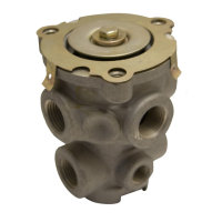
DELIVERY
PORT (4)
2 PIN SOLENOID
CONNECTOR
SUPPLY
PORT
FIGURE 1 - ATR-1
™
ANTILOCK TRACTION RELAY VALVE