®
SD-03-812
DESCRIPTION
The Bendix
®
E-2
™
and E-3
™
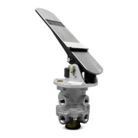
brake valves are single circuit
brake valves that provide the driver with single point control
of the service braking system. The valve can be either treadle
operated or fitted with a lever for a linkage connection to a
conventional brake pedal. Movement of the treadle or pedal
controls the graduated application and release of air pressure
to the vehicle brake actuators, applying or releasing the
vehicle brakes.
The E-2
™
and E-3
™
brake valves utilize a rubber spring
confined in a retainer, resulting in reduced plunger travel as
compared to previous design single circuit brake valves.
The E-3
™
brake valve differs from the E-2
™
valve in that it
employs a different piston (see insert Fig. 1), which requires
greater plunger travel. Because of the greater plunger travel,
the E-3
™
valve provides less sensitivity in the 0-40 psi
application range as compared to the E-2
™
valve. Other than
the different pistons, the E-2
™
and E-3
™
valves are identical.
An identification washer, located under the retaining ring in
the valve’s exhaust port, provides a means of identifying the
E-2
™
and E-3
™
brake valve.
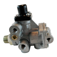
The E-2
™
and E-3
™
valves have an insert type inlet/exhaust
valve assembly which can be removed without disconnecting
air lines. An exhaust check valve in the bottom of the insert
prevents contaminants from entering the valve through the
exhaust port. An optional exhaust extension is available
should an exhaust carry-off line be required.
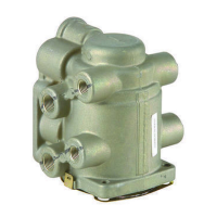
Porting consists of two (2) 1/2 inch p.t. supply ports, four (4)
3/8 inch or 1/2 inch p.t. delivery ports, and two (2) 1/4 inch
p.t. accessory ports (in the supply portion of the valve).
OPERATION
Applying
Applying the treadle or pedal exerts a force on the plunger,
rubber graduating spring and piston. The downward
movement of the piston causes the piston stem (which is
the exhaust seat) to contact the valve, closing the exhaust.
As the exhaust closes, the inlet valve moves away from its
seat. Air pressure is then allowed to flow by the inlet valve,
out the delivery ports and to the brake actuators, applying
the brakes.
Balanced
When the air pressure in the cavity beneath the piston and
the air pressure being delivered to the brake actuators equals
the mechanical force on the top of the piston, the piston
lifts and the inlet valve closes, cutting off any further flow of
air from the supply line through the valve. The exhaust
remains closed, preventing any escape of air through the
exhaust port.
Bendix
®
E-2
™
& E-3
™
Brake Valves
FIGURE 1 E-3
™
BRAKE VALVE (SECTIONAL VIEW)
RETAINER
O-RING
PISTON
RETURN
SPRING
RETAINING
RING
PRELOAD
SPRING
EXHAUST CH.
VALVE SEAT
INLET/EXHAUST
VALVE
CAP SCREW
INSERT ASS’Y
SPRING SEAT
WASHER
RUBBER SPRING
RETAINER
VALVE SPRING
O-RING
O-RING
DIAPHRAGM
WASHER
SCREW
11
10
6
2
3
1
4
12
8
9
21
20
19
18
17
16
15
14
13
MOUNTING
PLATE
TREADLE
AUXILIARY
PORTS (2)
DELIVERY
PORTS (4)
EXHAUST
SUPPLY
PORTS (2)
7
PISTON
E-2
™
- E-3
™
BRAKE VALVE