4
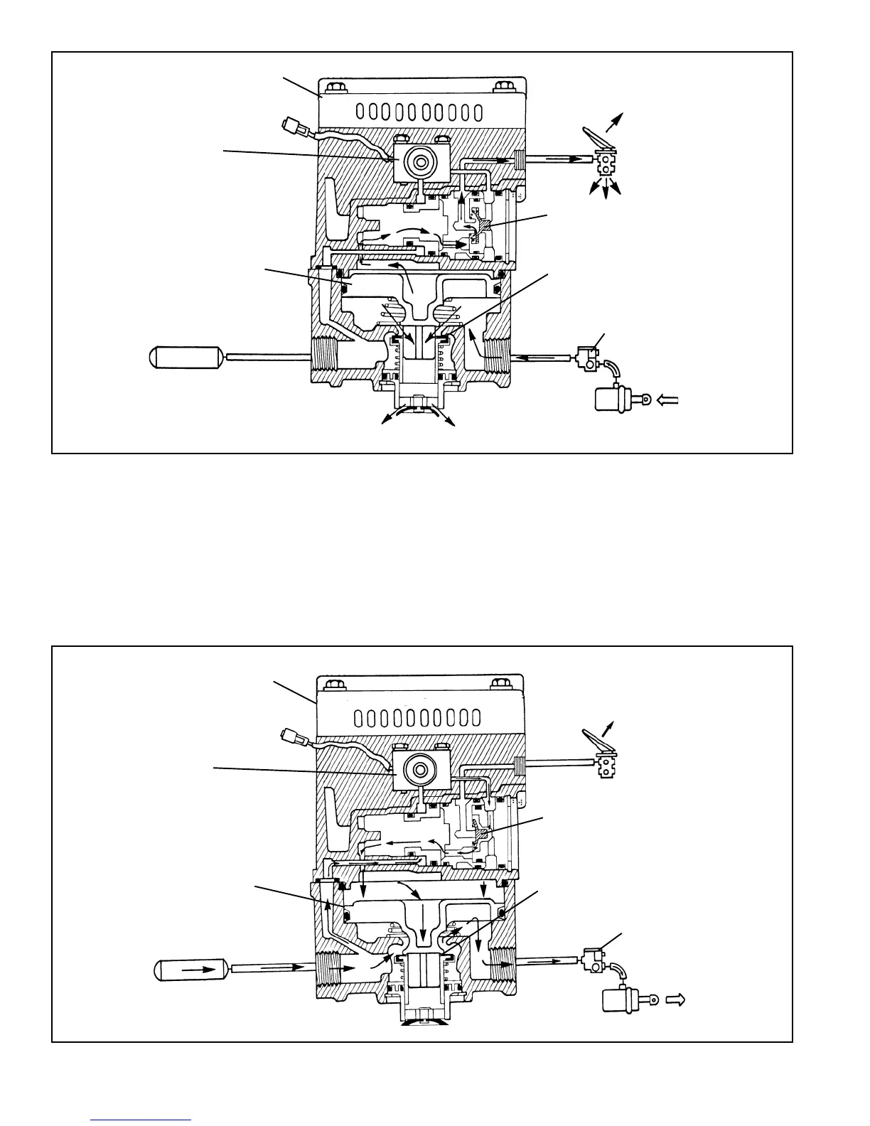
FIGURE 6 - SERVICE BRAKES RELEASING
FIGURE 7 - TRACTION CONTROL BRAKE APPLICATION
SERVICE BRAKES RELEASING (FIGURE 6)
When the brake application is released, air from above the
relay piston flows back through the blend back and service
pistons to the foot brake valve and is exhausted. As air
pressure is reduced above the relay piston, pressure beneath
it lifts the piston away from the exhaust valve and opens the
exhaust passage. Air from the service brake chambers
returns to the ATR-1
™
valve and flows out the open exhaust.
TRACTION CONTROL SERVICE APPLICATION
(FIGURE 7)
GENERAL
While under the control of an antilock traction controller, the
ATR-1
™
valve’s solenoid is able to initiate a brake application
that allows the traction system to control wheel spin upon
acceleration under 25 mph. When wheel spin is detected
BRAKE
VALVE
RELAY PISTON
TRACTION
SOLENOID
MODULATOR
INLET EXHAUST
CONTROLLER
REAR AXLE
RESERVOIR
SPRING BRAKE
EXHAUST
CHECK VALVE
RELAY PISTON
TRACTION
SOLENOID
INLET EXHAUST
CHECK VALVE
CONTROLLER
REAR AXLE
RESERVOIR
SPRING BRAKE
MODULATOR
BRAKE
VALVE
 Loading...