EasyManua.ls Logo

BENDIX Wingman FLR10 - User Manual

BENDIX Wingman FLR10
8 pages
Print Icon
To Next Page IconTo Next Page
Loading...
1
Installation Instructions
Bendix
®
Wingman
®
FLR10
to FLR20
Radar Changeover Kits
PREPARATION
Park the vehicle on level ground. Switch off the ignition and
disconnect the battery. See the General Safety Guidelines.
Read and understand this document before beginning work.
TYPICAL TOOLS REQUIRED
Torx T20 Driver; Wire Cutter; Wire Stripper; Deutsch Crimp
Tool HDT-48-00; 13mm Socket and Driver; Wire Brush.
GENERAL SAFETY GUIDELINES
WARNING! PLEASE READ AND FOLLOW THESE INSTRUCTIONS
TO AVOID PERSONAL INJURY OR DEATH:
When working on or around a vehicle, the following guidelines should be observed AT ALL TIMES:
Park the vehicle on a level surface, apply the
parking brakes and always block the wheels.
Always wear personal protection equipment.
Stop the engine and remove the ignition key
when working under or around the vehicle.
When working in the engine compartment,
the engine should be shut off and the ignition
key should be removed. Where circumstances
require that the engine be in operation, EXTREME
CAUTION should be used to prevent personal
injury resulting from contact with moving,
rotating, leaking, heated or electrically-charged
components.
Do not attempt to install, remove, disassemble
or assemble a component until you have read,
and thoroughly understand, the recommended
procedures. Use only the proper tools and
observe all precautions pertaining to use of those
tools.
If the work is being performed on the vehicle’s
air brake system, or any auxiliary pressurized air
systems, make certain to drain the air pressure
from all reservoirs before beginning ANY work
on the vehicle. If the vehicle is equipped with a
Bendix
®
AD-IS
®
air dryer system, a Bendix
®
DRM
dryer reservoir module, or a Bendix
®
AD-9si
®
air
dryer, be sure to drain the purge reservoir.
Following the vehicle manufacturers
recommended procedures, deactivate the
electrical system in a manner that safely removes
all electrical power from the vehicle.
Never exceed manufacturers recommended
pressures.
Never connect or disconnect a hose or line
containing pressure; it may whip and/or cause
hazardous airborne dust and dirt particles. Wear
eye protection. Slowly open connections with
care, and verify that no pressure is present. Never
remove a component or plug unless you are
certain all system pressure has been depleted.
Use only genuine Bendix
®
brand replacement
parts, components and kits. Replacement
hardware, tubing, hose, ttings, wiring, etc. must
be of equivalent size, type and strength as original
equipment and be designed specifi cally for such
applications and systems.
Components with stripped threads or damaged
parts should be replaced rather than repaired.
Do not attempt repairs requiring machining or
welding unless specifi cally stated and approved
by the vehicle and component manufacturer.
Prior to returning the vehicle to service, make
certain all components and systems are restored
to their proper operating condition.
For vehicles with Automatic Traction Control
(ATC), the ATC function must be disabled (ATC
indicator lamp should be ON) prior to performing
any vehicle maintenance where one or more
wheels on a drive axle are lifted off the ground
and moving.
The power MUST be temporarily disconnected
from the radar sensor whenever any tests USING
A DYNAMOMETER are conducted on a vehicle
equipped with a Bendix
®
Wingman
®
system.
You should consult the vehicle manufacturer's operating and service manuals, and any related literature,
in conjunction with the Guidelines above.
Kit Contents
Description Qty
Bendix
®
FLR20
Reman Radar . . . . . . . . . . 1
Adjusters/Screws. . . . . . . . . . . . . . . . . . 1
Bracket . . . . . . . . . . . . . . . . . . . . . . . 1
Harness Adapter . . . . . . . . . . . . . . . . . 1
Deutsch Connector Mating Kit . . . . . . . . . . 1
Upgrade Tag (BW1829) . . . . . . . . . . . . . . 1
Question and Answer IconNeed help?

Do you have a question about the BENDIX Wingman FLR10 and is the answer not in the manual?

Overview

This document describes the Bendix® Wingman® FLR10™ to FLR20™ Radar Changeover Kits, providing detailed instructions for the installation, preparation, and alignment of the Bendix® FLR20™ Radar.

Function Description:

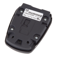
The Bendix® Wingman® FLR10™ to FLR20™ Radar Changeover Kits facilitate the upgrade of an existing FLR10™ radar system to the newer FLR20™ radar. This changeover is crucial for maintaining optimal performance of advanced driver-assistance systems (ADAS) in commercial vehicles, such as collision mitigation and adaptive cruise control. The FLR20™ radar is a remanufactured unit, ensuring reliability and cost-effectiveness. The kit includes all necessary components for the upgrade, such as the FLR20™ reman radar, adjusters/screws, bracket, harness adapter, Deutsch connector mating kit, and an upgrade tag (BW1829). The primary function of the radar is to detect objects in the vehicle's path, providing data to the ADAS for various safety functions.

Important Technical Specifications:

The kit is designed for the Bendix® FLR20™ Reman Radar. While specific technical specifications for the FLR20™ radar itself (e.g., range, field of view, frequency) are not detailed in this document, the installation process highlights key electrical and mechanical interfaces. The electrical connection uses a Deutsch ST06-6S connector with specific cavity designations: Ground (Cavity 1), CAN1_Hi (Cavity 2), CAN1_Lo (Cavity 5), and Power (Cavity 6). Cavities 3 and 4 are not used and are sealed with plugs. The wiring involves stripping wires to 0.250 to 0.312 inches and crimping Deutsch socket parts (0462-201-16141). Mechanical installation requires Torx T20 driver for screws, with a tightening torque of 30 in-lbs for adjuster mounting screws. The radar assembly is secured to the vehicle using two bolts, torqued to vehicle OE specifications. The alignment process requires specialized Bendix alignment tools (K065284 and K096579) and a steel clip (K073087) or steel plate (K105222) with stretch-release adhesive tape. Lateral alignment is achieved when measurements from the laser light line to symmetrical points on the vehicle's front are within 1/8" (3 mm). Vertical alignment is achieved when a digital inclinometer placed on the alignment tool reads 0° (±1.5°) from vertical.

Usage Features:

The installation process is designed to be straightforward, with clear steps for removing the old radar, preparing the harness, installing the new radar and bracket, and performing alignment.

  • Preparation: The vehicle must be parked on a level surface, with ignition off and battery disconnected. Personal protection equipment is mandatory.
  • Harness Adaptation: The existing wire harness is cut, and new Deutsch connectors are crimped onto the wires, following specific color-coded connections to the FLR20™ radar. Sealing plugs are used for unused cavities.
  • Radar and Bracket Installation: New adjuster assemblies are inserted into the bracket, and the FLR20™ radar is mounted onto these adjusters. The entire assembly is then installed onto the vehicle.
  • Radar Alignment: This is a critical step, involving both lateral and vertical alignment.
    • Lateral Alignment: Utilizes a laser-guided alignment tool to ensure the radar is centered. Measurements are taken from symmetrical points on the vehicle, and adjustments are made using a Torx T20 screwdriver until the laser light line is equidistant from both sides.
    • Vertical Alignment: Involves using a calibrated digital inclinometer to ensure the radar is level. Adjustments are made using a Torx T20 screwdriver until the inclinometer reads 0° (±1.5°).
  • Post-Installation: Re-installation of the vehicle's bumper (if removed) and checking for radar clearance are necessary. The removed FLR10™ radar must be returned for core credit using the supplied Bendix Upgrade Tag.
  • Safety Guidelines: Emphasizes critical safety practices, including blocking wheels, wearing PPE, disconnecting power, draining air pressure from air brake systems, and using genuine Bendix® parts. It also highlights the importance of deactivating the electrical system and avoiding contact with moving or heated components.

Maintenance Features:

The document primarily focuses on the installation and alignment of the FLR20™ radar, which itself is a remanufactured unit, implying a focus on replacement rather than in-depth repair of internal components.

  • Component Replacement: The instructions emphasize replacing damaged or corroded parts (e.g., bolts, components with stripped threads) rather than attempting repairs that require machining or welding, unless specifically approved by the manufacturer.
  • Core Return: The old FLR10™ radar is to be returned for core credit, indicating a remanufacturing or recycling program for used units.
  • Diagnostic Trouble Codes (DTCs): After lateral alignment, if active misalignment DTCs (codes 55, 56, or 57) are present, instructions are provided to clear them using Bendix® ACom® Diagnostics software and reset the alignment value.
  • Technical Support: Bendix provides a dedicated Technical Assistance Team (1-800-AIR-BRAKE, option 2) and email support (techteam@bendix.com) for troubleshooting and assistance, requiring specific product and vehicle information.
  • Online Training: Bendix offers online training resources at www.brake-school.com for continuous learning and best practices.
  • Regular Checks: The document implies that regular checks of radar alignment may be necessary as part of routine vehicle maintenance, especially if DTCs related to misalignment appear.
  • Adhesive Residue Removal: After alignment, any stretch-release adhesive residue from the steel clip or plate must be cleaned from the sensor.

BENDIX Wingman FLR10 Specifications

General IconGeneral
BrandBENDIX
ModelWingman FLR10
CategoryAutomobile Accessories
LanguageEnglish

Related product manuals