EasyManua.ls Logo

BENDIX AUTOVUE FLC-20 - User Manual

BENDIX AUTOVUE FLC-20
28 pages
Print Icon
To Next Page IconTo Next Page
Loading...
1
®
Bendix
AutoVue
®
FLC-20
Camera
SD-64-20124
1.0 DESCRIPTION
The Bendix
AutoVue
®
FLC-20
camera is a component
used in many Bendix safety systems, including:
The AutoVue
®
Lane Departure Warning (LDW) System by
Bendix CVS; and
The Bendix
®
Wingman
®
Fusion
Active Safety System.
For more information about the Bendix Wingman Fusion
System, see Service Data Sheet, SD‑61‑4963. For free
downloads of Service Data Sheets, visit the Bendix website
at bendix.com.
This document covers installation, troubleshooting, and
replacement for this camera.
Bendix safety technologies complement safe driving
practices. No commercial vehicle safety technology
replaces a skilled, alert driver exercising safe driving
techniques and proactive, comprehensive driver
training. Responsibility for the safe operation of the
vehicle remains with the driver at all times.
The camera bracket
is attached to the
windshield, and the
camera snaps into it.
(See Section 3.1)
Camera Lens
Radar Sensor
Camera
Figure 1 – Bendix
AutoVue
®
FLC-20
Camera
Figure 2 – Operational View
Detected Forward
Vehicle
RADAR Beam
Road Lane Markings
Vehicle Equipped with the
Bendix
®
Wingman
®
Fusion
System
Bendix
AutoVue
®
FLC-20
Camera
Windshield-mounted Visible
Light Camera
Roof-mounted Telematics
Antenna
Front Bumper-Mounted
Radar Sensor
NOT TO SCALE
Camera View
(See SD-61-4963 for the Bendix
®
Wingman
®
Fusion
Active Safety System)
Question and Answer IconNeed help?

Do you have a question about the BENDIX AUTOVUE FLC-20 and is the answer not in the manual?

Summary

Introduction and Safety

Product Description

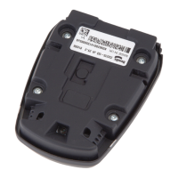
Provides a general description of the Bendix AutoVue FLC-20 camera and its applications.

General Safety Guidelines

Essential safety instructions to prevent injury or death during vehicle maintenance and operation.

Troubleshooting the FLC-20 Camera

Troubleshooting Safety Guidelines

Specific safety precautions to be observed during troubleshooting procedures.

DIU System Icons and Status

Explains Driver Interface Unit (DIU) icons indicating system status, initialization, and errors.

Camera Test Image Procedure

Steps to capture a test image using diagnostic software to check camera functionality.

Comprehensive Troubleshooting Steps

Covers disabling LDW, diagnostic trouble codes, ACom software, power, and communication issues.

Installation and Maintenance

Windshield Mounting Instructions

Detailed instructions for top and bottom mounting of the camera bracket on the windshield.

Camera and Bracket Removal Procedures

Step-by-step guide for safely removing the camera and its mounting bracket.

Maintenance and System Notes

Covers basic maintenance, camera interchangeability, and telematics wiring considerations.

Appendices and References

Appendix A: Diagnostic Code References

Table of SPN/FMI codes, DTCs, and their corresponding service action codes.

Appendix B: System Component Schematic

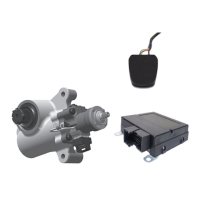
Provides a schematic diagram of the Bendix Wingman Fusion system components.

Appendix C: Controller Configuration Changes

Details controller configuration parameters and update procedures.

Overview

The Bendix™ AutoVue® FLC-20™ Camera is a critical component in various Bendix safety systems, including the AutoVue® Lane Departure Warning (LDW) System and the Wingman® Fusion™ Active Safety System. This windshield-mounted visible light camera works in conjunction with a front bumper-mounted radar sensor to detect forward vehicles and road lane markings, providing essential data for active safety features.

Function Description:

The primary function of the FLC-20 camera is to capture visual data of the road ahead, which is then processed by the Mobileye® System-on-Chip EyeQ® processor with state-of-the-art vision algorithms. This processing enables the detection of lane markings for the LDW system and contributes to the overall situational awareness for the Wingman® Fusion™ Active Safety System. The camera's input is crucial for features like lane departure warnings, and in the context of the Fusion system, it works with radar data to identify and track objects in the vehicle's path.

The camera communicates with other Electronic Control Units (ECUs) in the vehicle, sending and receiving J1939 messages and private network messages. These communications are vital for the integrated operation of the safety systems. If expected messages are not received or if signal values are out of the normal operating range, Diagnostic Trouble Codes (DTCs) will be set, indicating potential issues within the system.

The system includes a Driver Interface Unit (DIU) that displays icons to inform the driver about the system's status, such as "System Busy" during initialization, "Camera Impaired" if detection problems occur (e.g., due to sun-glare, a dirty windshield, or obstructions), and "Normal Operation" when actively seeking or tracking lane markings. A specific icon also indicates when a DTC has been set.

Important Technical Specifications:

  • Power Supply: The camera operates on a nominal voltage of 14V/28V (9-32V) for module power and 14V/28V (7-32V) for ignition wake-up.
  • Current Consumption: Module power draws 200mA/100mA, while ignition wake-up draws 20mA/10mA.
  • Communication Protocols: The camera utilizes J1939 for vehicle controller communication and private communications for interaction with the Bendix® Wingman® Fusion™ system.
  • Connectors: It features an Amphenol 4-pin shielded connector (P/N HSD-NARP-PCB-12B) and a JST 9-pin rectangular connector (P/N SM09B-HCHK-TB(LF)(SN)).
  • Processor: Powered by the Mobileye® System-on-Chip EyeQ® processor.
  • Operating Temperature Range: For installation and re-installation, the ambient temperature must be between 50-100°F (10-38°C).

Usage Features:

  • Diagnostic Software: The Bendix® ACom® Diagnostic Software (PC-based) provides technicians with access to ECU diagnostic information and configuration capabilities. It allows for reading DTCs, viewing camera test images ("snapshots") to check for obstructions, and clearing DTCs after troubleshooting.
  • Lane Departure Warning (LDW) Enable/Disable Switch: Vehicles equipped with the LDW system have a switch (Bendix design or similar OEM switch) to temporarily disable the LDW warnings, particularly useful in areas with non-standard or overlapping road markings like construction zones.
  • Video Data Transmission: For vehicles with the LDW switch hard-wired to the SafetyDirect® by Bendix CVS Web Portal Processor and a functioning On Board Computer (OBC)/Telematics system, depressing the enable/disable switch for six seconds activates a manual request to transmit buffered video data (last five seconds and next five seconds).
  • System Status Display: The Driver Interface Unit (DIU) or OE vehicle dash display provides visual alerts and icons for system status, including initialization, impaired operation, normal operation, and DTC presence.
  • Calibration: The camera requires calibration, and specific parameters (FoeX, FoeY, Roll angle, Camera height, Grabbing shift) can be configured using the ACom Diagnostic Software. Calibration values are critical for accurate system performance.

Maintenance Features:

  • Troubleshooting: The manual provides comprehensive troubleshooting procedures for various DTCs, categorized by service action codes (A, B, C, E, I, M, N, P, Q, V). These procedures cover issues related to power supply, ignition voltage, wiring harnesses (J1939 and private communications), camera mounting, software versions, and sensor calibration.
  • Wiring Harness Checks: Detailed instructions are provided for checking wiring circuits for damage, corrosion, shorts, opens, and proper resistance (e.g., 120 ohms for private communications, 60 ohms for J1939).
  • Camera Removal and Installation: Specific steps are outlined for safely removing the camera from its bracket and installing a new one. This includes engaging the top of the camera, rotating it into the bracket until it clicks, and verifying full engagement. For removal, two flat-blade screwdrivers are used to gently pry against retaining clips.
  • Bracket Removal: The preferred method for bracket removal involves using a heat-gun to soften the adhesive on the windshield, followed by gentle prying.
  • Windshield Cleaning: Regular cleaning of the windshield is essential to ensure a clear view for the camera. The camera lens should be protected during cleaning.
  • Replacement Parts: Only genuine Bendix® brand replacement parts, components, and kits should be used. For camera brackets, only Bendix-approved windshield adhesive and specific part numbers (K109285) are recommended.
  • Camera Interchangeability: Cameras are designed for specific vehicle models and model years. Interchanging cameras between different models is not recommended as it can lead to DTCs and performance degradation.
  • Telematics Wiring: An important note advises disconnecting the OBC/T harness if an OBC/T system is not in use to prevent interference with the SafetyDirect® by Bendix CVS Web Portal Processor.
  • Technical Support: Bendix provides technical support via phone (1-800-AIR-BRAKE, option 2) and email (techteam@bendix.com) for assistance with troubleshooting and configuration.

BENDIX AUTOVUE FLC-20 Specifications

General IconGeneral
BrandBENDIX
ModelAUTOVUE FLC-20
CategoryAutomobile Accessories
LanguageEnglish

Related product manuals