7
2.7 STARTING BENDIX
®
ACOM
®
DIAGNOSTIC SOFTWARE
The Bendix
®
ACom
®
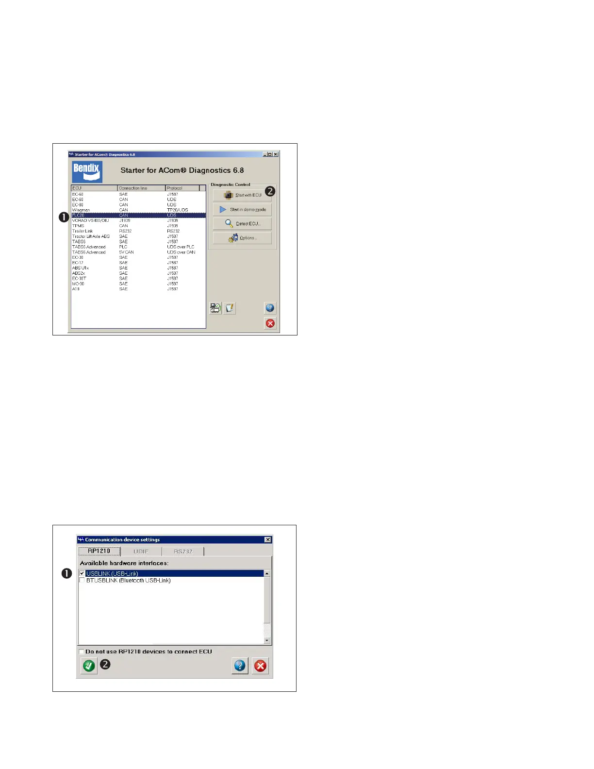
Diagnostic Software can be started
from the desktop shortcut, or from the main Windows
®
screen with “Start...Programs...Bendix...ACom Diagnostic
Software.” See Figure 7. To begin, the technician selects
“FLC-20” from the starter screen, then “Start with ECU”
from the Diagnostic Control panel.
Figure 7 – Starting Bendix
®
ACom
®
Diagnostic
Software
NOTE: When using ACom Diagnostic Software for the
rst time, the service technician will be asked to select the
communication adapter for both the Bendix
™
AutoVue
®
FLC‑20
™
camera and Bendix
®
ABS and stability controllers.
While both controllers will use the same physical adapter,
the technician will need to indicate which communication
protocol to use for each. Once a successful connection
has been made, these steps will no longer be necessary.
The Bendix ACom Diagnostic Software for ABS User
Guide is available for download at bendix.com and
should be used as a reference to all functions of the
ACom service tool. See Figure 8.
.
Figure 8 – Bendix ACom Diagnostic Software –
Hardware Interface Screen
2.8 READING DIAGNOSTIC
TROUBLE CODES (DTCs)
If the system generates a Diagnostic Trouble Code (DTC),
where a lamp or icon is illuminated on the instrument
cluster, use a current version of ACom Diagnostic Software
to troubleshoot. Select “FLC-20” from the starter screen,
then “Start with ECU”. Click “DTC” to show the DTCs.
See Section 2.10 for a complete table showing DTCs and
troubleshooting information.
2.9 DIAGNOSTIC TROUBLE CODES (DTCs)
Use a J1939 detection software to nd the DTC code(s)
and use the Table in Section 2.10 to nd the service action
code to use. The service actions to take may then be found
in the Table shown in Section 2.11.
If the troubleshooting devices available to the technician
provide Suspect Parameter Number (SPN) and
Failure Mode Identier (FMI) code combinations, refer to
Appendix A.