16
2.13 SERIAL DATA (PRIVATE
COMMUNICATIONS)
TROUBLESHOOTING PROCEDURE
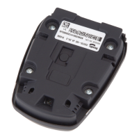
1. Take all measurements at the harness connector unless
otherwise indicated.
Do not insert any probe into the pin on the mating
connector of the sensor that is greater than the width
of a terminal. Damaged connector pins will require the
replacement of the harness.
2. Check for damaged or reversed Private Communications
wiring.
If the Private Communications HIGH, or Private
Communications LOW, wiring circuits are damaged,
such as shorting together, the entire Private
Communications link will be lost. The problem may be
intermittent, enabling the Private Communications link
to operate normally sometimes. In this event, multiple
diagnostic trouble codes may be logged in the camera
and radar.
If the Private Communications HIGH, and Private
Communications LOW, wiring circuits are reversed,
communication over the entire Private Communications
link will be lost. Devices that use the aected network
will not be able to transmit or receive messages on
that network.
3. Check for corroded or damaged wiring connector
problems such as opens or shorts to voltage or ground.
If the connector terminals are corroded, this may be
an indication of water intrusion into the wiring system
and possibly the camera sensor. Replacement of the
entire harness is recommended. If the terminals of the
camera sensor are corroded, replacement of the sensor
is recommended.
4. Check for other Private Communications devices
which may be inhibiting communication. The service
technician should consult the procedures for Private
Communications troubleshooting. The device’s power
should be removed and measurements made at the
Electronic Control Unit (ECU) pins for shorts to ground
and power pins and resistance between the Private
Communications HIGH or Private Communications
LOW input circuits.
5. Unplug the camera harness. With the ignition switch
o, measure the resistance (ohms) using a multimeter
between harness pins 6 and 7. The reading should be
approximately 120 ohms. If it is not, the vehicle wiring
should be investigated.
2.14 POWER TROUBLESHOOTING
PROCEDURES
1. Unplug the camera. With the ignition switch ON, using
a multimeter, measure the voltage, between harness
pin 9 and ground. The measurement should indicate
10 to 16 VDC (Volts DC). If this is not the case, the
vehicle wiring should be investigated using procedures
described by the manufacturer.
2. Unplug the camera. With the camera ignition switch
OFF, using a multimeter, measure the voltage, between
harness pin 9 and ground. The measurement should
indicate zero VDC. If this is not the case, the vehicle
wiring should be investigated using procedures
described by the manufacturer.
3. Unplug the camera. With the ignition switch OFF, using
a multimeter, measure the voltage, between harness
pin 1 and ground. The measurement should indicate
10 to 16 VDC. If this is not the case, the vehicle wiring
should be investigated using procedures described by
the manufacturer.
2.15 COMMUNICATIONS (J1939) TEST AND
TROUBLESHOOTING PROCEDURES
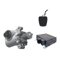
The Bendix
™
AutoVue
®
FLC-20
™
camera requires several
J1939 messages from various Electronic Control Units
(ECUs). The camera will set a Diagnostic Trouble Code
(DTC) if one of the messages from one of the expected
ECUs is not present. Go to the Service Data Sheet listed
below for the particular ECU for full troubleshooting
information.
Reference Documents:
• The Bendix
®
Wingman
®
Fusion
™
Active Safety System
(SD‑61‑4963)
• The Bendix
®
ESP
®
EC‑80
™
Controller (SD‑13‑4986)
• The SafetyDirect
®
by Bendix CVS Web Portal
Processor (SD‑65‑21025)
1. Take all measurements at the harness connector unless
otherwise indicated.
Do not insert any probe into the pin on the mating
connector of the sensor that is greater than the
dimension of the mating connector. Damaged connector
pins will require the replacement of the harness.
2. Check for damaged or reversed J1939 wiring.
If the J1939 HIGH, or J1939 LOW, wiring circuits are
damaged, such as shorting together, the entire J1939
link will be lost. The problem may be intermittent,
enabling the J1939 link to operate normally sometimes.
If this occurs, multiple diagnostic trouble codes will be
logged in multiple engine and vehicle controllers.