17
2.16 PRIVATE COMMUNICATIONS
NETWORK TEST PROCEDURE
The Bendix
™
AutoVue
®
FLC-20
™
camera requires private
network messages to and from the Bendix
®
Wingman
®
Fusion
™
system. The camera will set a Diagnostic Trouble
Code (DTC) if these messages are not present, or if there
is a problem with the private communications system. Go
to the Bendix Wingman Fusion System Service Data Sheet
(SD‑61‑4963) for full troubleshooting information.
2.17 TROUBLESHOOTING
WIRING HARNESSES
All wire harness connectors must be properly seated to
maintain electrical connectivity. Push the mating connectors
until they click. When replacing a Bendix Fusion FLC-20
camera, check that the wire harness connectors are free
of damage, including corrosion, before plugging into a new
camera. Check for corroded or damaged wiring connector
problems such as opens or shorts to voltage or ground.
If the connector terminals are corroded, this may be an
indication of water intrusion into the wiring system and
possibly into the camera (presumably from a cracked
windshield). Replacement of the entire harness is
recommended. If the terminals of the camera are corroded,
replacement of the camera is recommended.
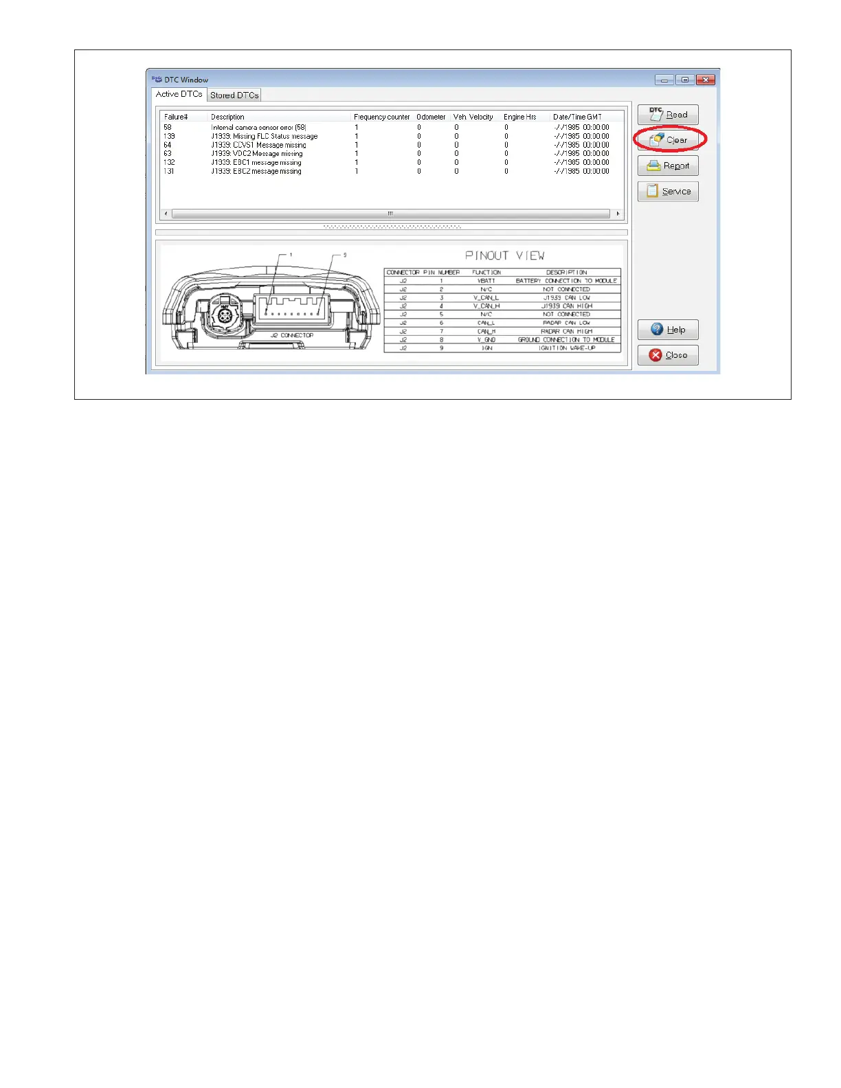
2.18 CLEARING DIAGNOSTIC
TROUBLE CODES (DTCs)
Cycle the ignition power, or use the Bendix
®
ACom
®
Diagnostic Software (version 6.8.3.2 or higher) to clear
DTCs after troubleshooting – and correcting – any problem
with the system. See Figure 10.
If the J1939 HIGH, and J1939 LOW, wiring circuits are
reversed, communication over the entire J1939 link will
be lost. Devices that use the aected network will not be
able to transmit or receive messages on that network.
3. Check for poorly-crimped, corroded, contaminated, or
damaged wiring connector problems such as opens or
shorts to voltage or ground.
If the connector terminals are corroded or damaged, this
may be an indication of water intrusion into the wiring
system and possibly into the sensor. Replacement of
the entire harness is recommended. If the terminals of
the sensor are corroded, replacement of the sensor is
recommended.
4. Check for other J1939 devices which may be inhibiting
J1939 communication. The service technician should
consult the vehicle manufacturer’s procedures for
other J1939 troubleshooting procedures. The device’s
power should be removed and measurements made at
the ECU pins for shorts to ground and power pins and
resistance between the J1939 HIGH or J1939 LOW
input circuits.
5. Unplug the camera harness. With the camera ignition
OFF, measure the resistance (ohms) using a multimeter
between harness pins 3 and 4. The reading should
be approximately 60 ohms. If this is not the case, the
vehicle wiring should be investigated.
Figure 10 – Clear Diagnostic Trouble Codes (DTC[) Button