1
S-1483 ©2006 Bendix Commercial Vehicle Systems LLC 10/2006 Printed in U.S.A. All Rights Reserved.
Prior to installation or performing service to ABS
controllers always perform the following steps:
1. Inspect the vehicle for damage, chafing, etc. to
current ABS unit, hoses or wiring and adjust routing of
replacement installation as necessary.
2. Turn power off.
3. Drain the air pressure from all reservoirs.
4. Remove as much contamination as possible prior to
disconnecting electrical connections and air lines.
5. Note the original controller assembly mounting position
on the vehicle.
6. Follow all General Maintenance Precautions as found
below in these instructions.
REMOVING THE ORIGINAL CONTROLLER
1. Disconnect the ECU connector and any modulator
connector from the controller.
2. Remove all air lines connected to the unit. (Use spray
lubricant on the swivel fi ttings of the delivery lines where
necessary before attempting to remove them.)
3. Remove the controller assembly from the vehicle by
removing the mounting bracket nuts or by rotating
the entire assembly counterclockwise from the tank
mount.
4. Disconnect the ABS sensors and remove the existing
harness. Bendix requires that only Bendix wheel speed
sensors be used for Bendix ABS systems.
WHEEL SPEED SENSOR REPLACEMENT
Due to the critical safety function provided by any ABS
product, Bendix does not assume responsibility for antilock
system reliability or performance issues in situations where
substitute non-Bendix
®
ABS components, not supplied by
Bendix (for example, substituting a non-Bendix
®
wheel
speed sensor or modulator valve) are used on a vehicle
equipped with Bendix
®
ABS. In addition, use of alternate
components in place of genuine Bendix components could
lead to rejection of ABS warranty claims. See Bulletin
TCH-013-009 for more details.
INSPECTION
Inspect the location selected for installation and clean as
necessary.
NOTE: Inspect all components, including the
replacement trailer ABS module, for any external
damage, such as cracked valve ports, electronic
housings, etc. Any components found to be damaged
should not be installed on the vehicle and must be
replaced.
INSTALLATION
1. Position and secure the unit in the original mounting
orientation: (The exhaust port must point straight down.)
Tank (nipple) mount unit - Install the nipple fi tting into the ABS
module supply port. Then rotate the entire assembly into the
tank port until secure. Over-torquing of the tank nipple could
cause damage to the Module.
Frame (bracket) mount unit - Torque the mounting nuts to
180-220 in-lbs.
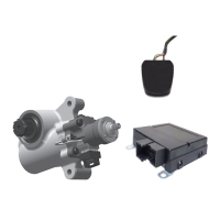
FIGURE 1 - KIT (AND OPTIONAL DOLLY) COMPONENTS
KIT CONTENTS
Item . . Description . . . . . . . . . . . Qty.
No.
1. . . . ABS Power Harness . . . . . . . 1
2. . . . Wheel Speed Sensor Harness. . 2
3. . . . Trailer ABS Module . . . . . . . 1
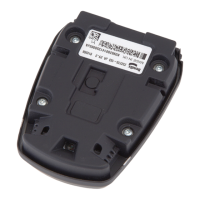
4. . . . Identifi cation Label. . . . . . . . 1
(not shown) Service Data sheet. . . . . . . . 1
1
4
3
2
Cover
Release
Tab
Bendix
®
DC-4™
Double
Check
Valve
Bendix
®
TR-3™
Parking
Brake
Control
Valve
EXTRA COMPONENTS USED FOR TYPICAL DOLLY
INSTALLATION
Installation Instructions
Bendix
®
Trailer ABS Service Replacement Kit Intended for Service Replacement
of Bendix
®
MC-12
™
or MC-30
™
Controller Assemblies for 2S/1M Trailer ABS
(2 alternate harness style)