2
2. Reconnect all air lines and plugs to the modulator-valve
assembly. Make certain that no thread sealing material
enters the valve. All air lines and fi ttings should be checked
for leaks prior to returning the vehicle to service.
3. Reconnect the ECU and sensor electrical connectors to
the unit. Slide the cover locking tab to gain access to the
internal connections. Apply a moderate amount of non-
conductive electrical grease to each connector pin before
reconnecting.
4. Install the new harness, starting at the ECU and properly
secure the harness every 18 inches to the power connector
location. Replace and lock the cover.
5. Where the harness length is more than needed, reroute
harness, or tie extra harness as shown in Figure 3.
6. The new controller may need to be reconfigured
for proper operation. See the Service Data sheet
SD-13-4767 included in the kit for more details. Leakage
and Operational Tests must be performed before returning
the vehicle to service.
LEAKAGE AND OPERATIONAL TESTS
1. Before performing leak tests, block the wheels.
2. Fully charge the air brake system and verify proper brake
adjustment.
3. Make several trailer brake applications and check for
prompt application and release at each wheel.
4. Check the modulator-valve body and all air hose fi ttings
for leakage by spraying each area with a soap solution:
- Check the ABS solenoid body with the trailer service
brakes fully applied. If leakage is excessive, replace the
entire ABS module. A single 1” bubble within 3 seconds
is permitted.
- Check the relay exhaust port and the area around the
retaining ring with the trailer service brakes released. A
single 1” bubble within 3 seconds is permitted.
- Check the relay exhaust port and the area around the
retaining ring with the trailer service brakes fully applied.
A single 1” bubble within 3 seconds is permitted.
If excessive leakage is detected at the relay exhaust
port, perform the following test before replacing the ABS
module:
Apply the trailer spring brakes. Recheck for leakage
around the exhaust port. If the exhaust port stops leaking,
this indicates a leak between the emergency and service
sides of the spring brake chamber. However, if the
relay exhaust port continues to leak, replace the entire
modulator-valve.
5. Apply power and monitor the controller power-up sequence
to verify proper system operation. The warning lamp
should come on for approx 2.5 sconds and then go out.
6. Calibrate and set odometer parameters if necessary using
a diagnostic tool.
7. Where a test track is available, test the ABS function by
making an abrupt stop from a vehicle speed of about 20
MPH to check for proper function. The wheels should not
enter a prolonged lock condition and ABS function should
be audible. It is the responsibility of the technician to
perform this test in a safe location.
ABS WIRING
The Bendix pigtail wiring harness and connectors are weather
resistant and sealed at the connector interface.
TROUBLESHOOTING
Fault information can be retrieved from the controller by using
blink code diagnostics shown on the yellow label included
in the kit, or a diagnostic tool. See the Service Data sheet
SD-13-4767 included in the kit for more details.
GENERAL MAINTENANCE PRECAUTIONS
WARNING! PLEASE READ AND FOLLOW THESE
INSTRUCTIONS TO AVOID PERSONAL INJURY OR
DEATH:
When working on or around a vehicle, the following
general precautions should be observed at all times.
1. Park the vehicle on a level surface, apply the parking
brakes, and always block the wheels. Always wear
safety glasses.
2. Stop the engine and remove ignition key when working
under or around the vehicle. When working in the
engine compartment, the engine should be shut
off and the ignition key should be removed. Where
circumstances require that the engine be in operation,
EXTREME CAUTION should be used to prevent
personal injury resulting from contact with moving,
rotating, leaking, heated or electrically charged
components.
Bundle Extra Wire
Length
Tie Wrap
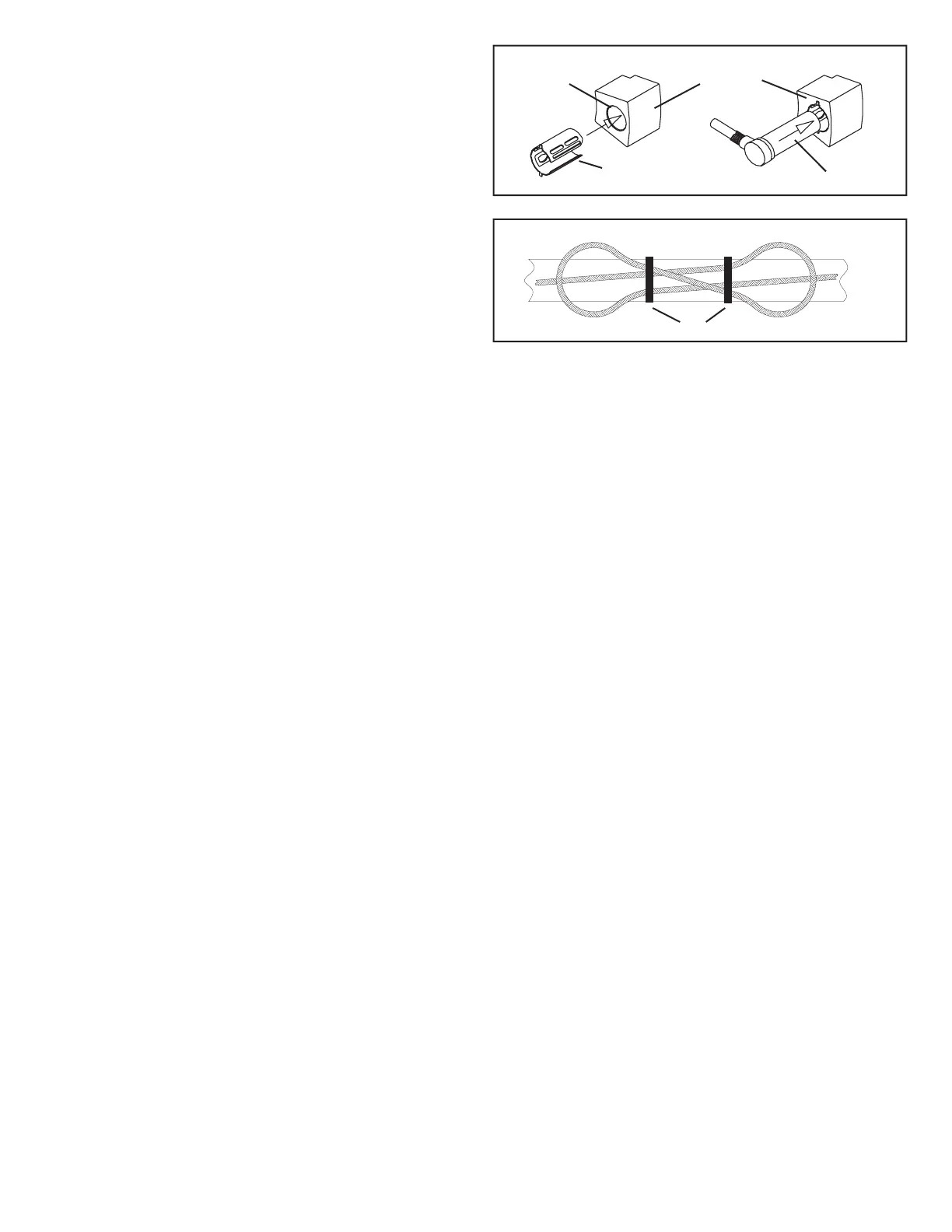
Wheel Speed Sensor
Sensor Clip
Block Bore
Speed Sensor
Mounting Block
FIGURE 3 - BUNDLING EXTRA WIRE LENGTH
FIGURE 2 - SENSOR CLIP AND SENSOR INSTALLATION
 Loading...