6
Appendix
Bendix
®
FLR20
™
Radar Alignment
LATERAL ALIGNMENT USING THE BENDIX
®
ALIGNMENT TOOL (CONTINUED)
NOTE: Complete these steps only if a lateral adjustment is necessary.
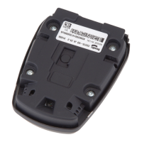
A7 With the Bendix alignment tool still in place, use the Torx T-20 screwdriver to turn by hand the driver-side stand-off
adjustment screw until the desired alignment is reached.
Use a Torx T-20 screwdriver here to
adjust for the lateral alignment
IMPORTANT:
Do not adjust
this stand-off!!
A8 Re-measure the distances from symmetrical points located at least 12” from the center line of the vehicle. Reverse
the tool for each measurement, until the values are the same [within 1/8” (3 mm)].
A9 After the lateral alignment procedure is complete, if there is an active misalignment DTC (codes 55, 56, or 57), use
the instructions in Bendix Service Data Sheet, SD-61-4960 (available from www.bendix.com) to clear the Bendix
®
Wingman
®
Advanced
™
system's Diagnostic Trouble Code (DTC) using the procedure in Section 4.4: Clearing
Diagnostic Trouble Codes (DTCs) and reset the alignment value by connecting the vehicle to a PC with Bendix
®
ACom
®
Diagnostics software and follow steps B4.4-20 to reset the alignment value. (Also, see Appendix H
of the Service Data Sheet.)
A10 IMPORTANT: Before returning the vehicle to service, check the vertical alignment.
A11 [The steel clip, or plate, and alignment tool should already be in place. See A1-2.]
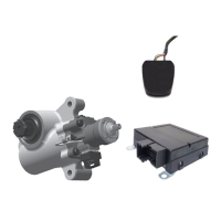
A12 Calibrate (or “zero”) the inclinometer on a horizontal section of the frame rail. Follow the manufacturer’s instructions
(typically digital inclinometers have a “SET” button for this purpose).
Calibrate (or “zero”) the Digital Inclinometer on a
Cab Frame Rail in the direction that the vehicle
travels.
Place the calibrated digital inclinometer onto the
surface of the tool, so that the tool is in the
same direction as it was on the rail. Verify
that the display shows 0° (± 1.5°) from vertical.
NOTE: Complete these steps only if a vertical adjustment is necessary.
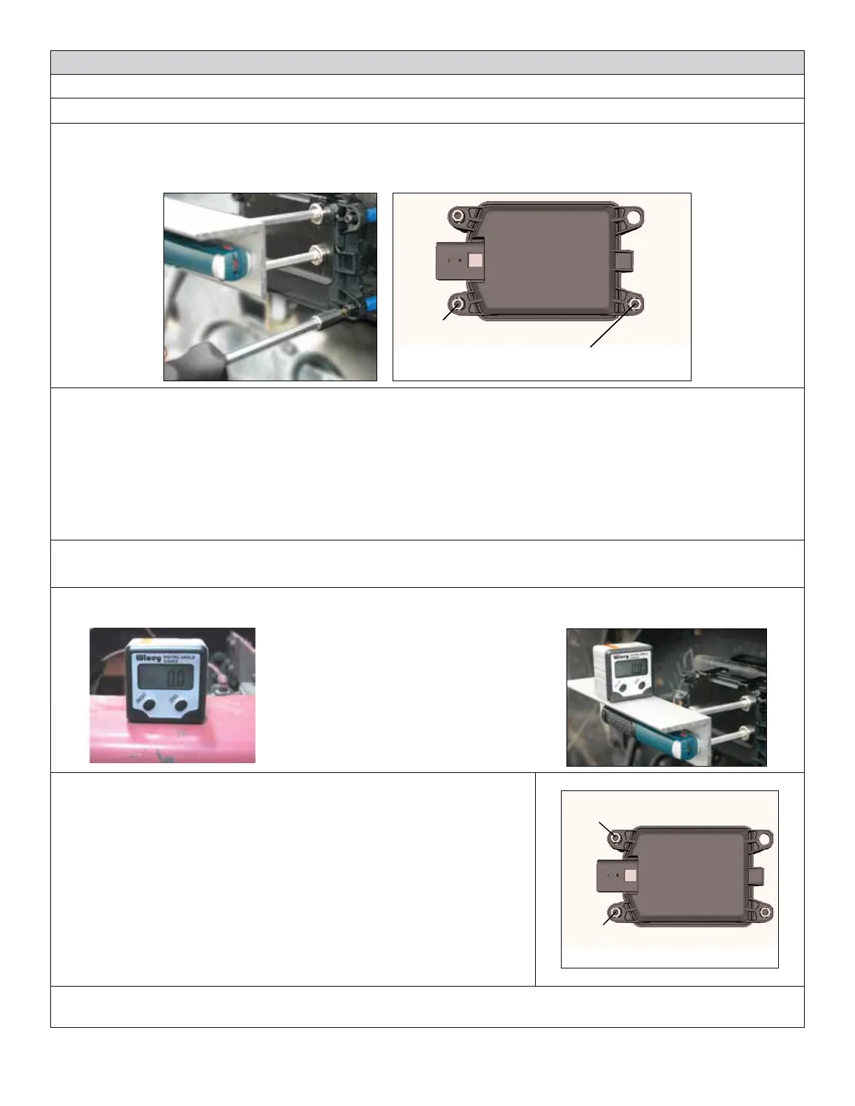
A13 With the Bendix alignment tool still in place, use the screwdriver to turn
by hand the top-left adjustment stand-off. See the Figure on the right.
During the adjustment, observe the digital display on the inclinometer
and turn the vertical alignment screw clockwise or counterclockwise
depending on the vertical direction (up or down) needed, until the
reading is near zero degrees.
A14 The radar is aligned vertically when the display is near zero (0°).
Note: The alignment process shown here is for Bendix alignment
brackets. For other brackets, similar alignment steps will be needed;
consult the vehicle manual for full instructions.
Use a Torx T-20 screwdriver here to
adjust for the vertical alignment
IMPORTANT:
Do not adjust
this stand-off!!
NOTE: The alignment process is complete after the vertical alignment has been checked (and adjusted, if
necessary), and the steel clip or plate is removed. You do not need to test-drive the vehicle.
 Loading...