Do you have a question about the BENSHAW RediStart EXEXMVRMX3 Series and is the answer not in the manual?
| Category | Controller |
|---|---|
| Input Frequency | 50/60 Hz |
| Protection Features | Overload, Overvoltage, Undervoltage, Phase Loss |
| Operating Temperature | -10°C to 50°C |
| Humidity | 5% to 95% (non-condensing) |
Safety measures for working with high voltage equipment.
Guidelines to prevent electrical shock and personal injury.
Precautions for safely moving and installing the starter unit.
Explains manual layout, symbols, and document structure.
Details on Benshaw services, documentation, and technical support.
Contact information for receiving technical assistance and support.
Explanation of the coding system used in model numbers.
Description of the starter's capabilities, features, and operational advantages.
Overview of starter configuration, system components, and general specs.
Detailed description of all terminal block connections and their functions.
Precision details for starter measurements like current, voltage, and frequency.
Catalog of all available motor protection functions and standards.
In-depth explanation of the I²t electronic overload protection system.
Ratings for temperature, humidity, and altitude for operation.
Derating information for operation at high altitudes.
Crucial steps and safety guidelines required before starting installation.
Site requirements and guidelines for electromagnetic compatibility.
Guidelines and best practices for all wiring connections.
Guidelines for physical mounting and routing of electrical wires.
Critical safety notes for meggering and high pot testing motors.
Information on wire gauges, cable connections, and lugs.
Procedures for proper mounting and polarity setting of current transformers.
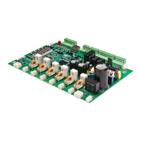
Identification of components on the main control card.
Identification of components on the input/output card.
Visual representation of all terminal block connections.
Wiring details for control power supply and output relays.
Diagrams and settings for connecting digital inputs.
Setup and configuration for analog signal processing.
Connecting and configuring the motor PTC thermistor input.
Steps for installing the remote LCD keypad and display unit.
Installing RTD modules and setting up RS-485 communication.
Introduction to the keypad, its display, and status indicator lights.
Explains the purpose and operation of each keypad button.
How to navigate and use the LCD display for starter operation.
Instructions on how to access and navigate through parameter groups.
How to view and interpret various meter readings on the display.
Procedures for accessing and interpreting fault and event logs.
Understanding different lockout messages and their potential causes.
Viewing alarm conditions and step-by-step guide for changing parameters.
Using jump codes, factory reset, and fault reset functions.
Overview of parameter organization and functionality.
Commonly adjusted parameters for initial starter setup.
Parameters related to motor control functions like start/stop and ramps.
Parameters dedicated to motor protection and safety features.
Configuration settings for digital and analog I/O.
Parameters for configuring RTD temperature monitoring inputs.
Parameters for various operational functions like Metering and Starter Type.
How parameter details are presented in the manual.
Setting the motor's full load amps and service factor.
Setting different overload trip classes for motor protection.
Choosing between Keypad, Terminal, or Serial control sources.
Configuring the remote control source for the starter.
Configuring initial and maximum current levels for acceleration ramp 1.
Setting acceleration ramp times and up-to-speed parameters.
Choosing the motor starting method and profile.
Configuring initial voltage, torque, or power for acceleration.
Setting maximum torque/power and choosing the acceleration shape.
Setting the initial kick current level for motor starting.
Choosing the motor stop mode and configuring deceleration parameters.
Setting final deceleration voltage and duration.
Selecting deceleration profile and setting DC brake current.
Setting DC brake time duration and delay before application.
Setting the trip time for motor PTC thermal protection.
Configuring distinct overload parameters for starting and running phases.
Setting the overload class for motor starting operations.
Setting the overload class for motor running operations.
Detailed configuration options for all digital inputs.
Detailed configuration options for all relay outputs.
Setting parameters for analog input trip type and level.
Configuring analog input delay time and signal span.
Configuring analog input offset and selecting analog output functions.
Configuring analog output scaling and offset values.
Configuring inline contactor behavior and bypass feedback parameters.
Disabling the keypad stop button to prevent accidental stops.
Setting up the starter's automatic start behavior.
Detailed explanation of the starter's overload protection system.
Guide to configuring motor overload settings for optimal protection.
How the motor overload functions during different operational modes.
How the system compensates for current imbalances and harmonics.
Compensation for motor temperature states during starting.
How RTD measurements influence motor overload calculations.
Mechanism to prevent overload trips during motor starts.
Configuring distinct overload parameters for starting and running phases.
How motor overload content reduces when the motor is stopped.
Motor cooling behavior and its effect on overload content while running.
Steps for performing an emergency overload reset.
Setting and utilizing the motor service factor for overload calculations.
General explanation of acceleration control and current ramp settings.
How to set up and use kick current for improved motor starting.
Explanation of the TruTorque acceleration control functionality.
Settings and timing for power control acceleration.
Understanding voltage ramps for motor starting.
Using two acceleration profiles and selecting tachometer ramp control.
How voltage control deceleration operates to stop the motor.
How TruTorque deceleration operates to smoothly stop the motor.
General information on starter braking methods and types.
Details of standard and heavy duty DC injection braking methods.
Illustrative wiring diagram for DC injection braking setup.
Configuration of DC brake timing and digital inputs for control.
Instructions for integrating the optional Hall Effect current sensor.
Explanation of the slow speed function and its operation.
How the starter functions when configured as an ATL starter.
Control logic for Hand/Off/Auto selector switches.
Simplified circuit diagrams for input/output connections.
Introduction to Modbus communication and network setup.
Essential safety rules and procedures for performing maintenance.
Recommended maintenance tasks and their frequency.
Utilizing LED indicators to diagnose starter issues.
Problem-solving guide for common starter operational issues.
Diagnosing issues related to the motor failing to start or produce output.
Steps for diagnosing and resolving motor acceleration problems.
Troubleshooting issues with motor deceleration and unexpected stops.
Resolving problems related to inaccurate meter readings.
Addressing miscellaneous operational problems and errors.
A comprehensive list of fault codes and their potential resolutions.
Steps for performing ohmmeter tests on components and checking fuses.
Testing SCR gate-to-cathode resistance for proper function.
Steps for replacing SCRs, including clamp assembly instructions.
General information and setup procedures for the Built-In Self Test.
Testing SCR gate firing sequence and simultaneous firing of all gates.
Procedures for resetting the system after BIST or cancelling the test.
Procedures for high potential testing and vacuum contactor maintenance.
Universal safety rules and PPE requirements for maintenance.
Detailed maintenance steps for contactors and power poles.
A table of event codes and their corresponding descriptions.
List of alarm codes and their relation to associated fault codes.
Comprehensive list of fault codes and troubleshooting steps.
List of optional parts, accessories, and common spare parts.
Product compliance statement with relevant EU directives.
Reference table for Modbus communication registers and addresses.
Settings and ranges for Quick Start and Control Function parameters.
Settings for motor protection parameters.
Settings for input/output and RTD temperature parameters.
Settings for various function group parameters.
Definitions of technical terms used throughout the manual.
Information regarding the 3-year warranty program and terms.
Detailed terms and conditions of the product warranty.