CIAO AT
56
CIAO AT
57
g. 5
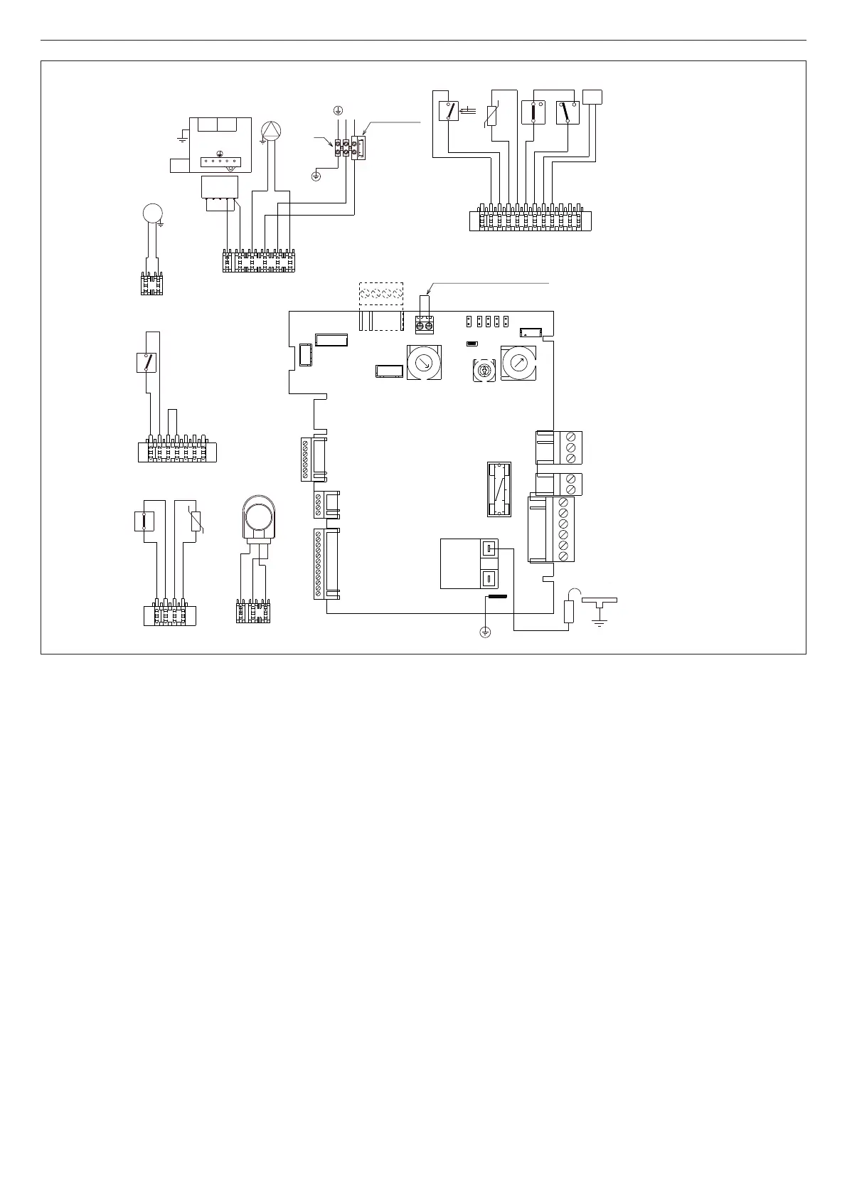
[EN] - Multi-row wiring diagram
"L-N" POLARISATION IS RECOMMENDED
marrone=brown / blu=blue / nero=black /
viola=purple / rosso=red / bianco=white
/ grigio=grey / rosa=pink/ risc=heating /
sanit=domestic hot water
A Gas valve
B 3.15 AF fuse
C 24V DC low voltage ambient thermostat
jumper
MP Control card with digital display and inte-
grated ignition transformer
P1 Potentiometer to select off - summer -
winter – reset / heating temperature
P2 Potentiometer to select domestic hot wa-
ter set point
P3 Potentiometer to select temperature reg-
ulation curve
JP1 Bridge to enable knobs for calibration
JP2 Bridge to reset the heating timer and log
maximum electrical heating in calibration
JP3 Bridge to select MTN - LPG
JP4 Absolute domestic hot water thermostat
selector
JP5 Bridge to select heating operation only
(not used)
JP6 Enabling management of flow switch or
storage tank thermostat/flow meter
(jumper closed = ow switch or storage
tank thermostat (heating-only versions) /
jumper open = ow meter)
F1 Fuse 2A T
F External fuse 3.15A F
M3 Terminal board for external connections
T.A. Ambient thermostat
E.A./R. Ignition/detection electrode
TR1 Ignition transformer
F Fan
P.F. Flue gas pressure switch
S.R. Primary circuit temperature probe (NTC)
T.L. Limit thermostat
OPE Gas valve operator
P Pump
3V 3-way valve servomotor
F.L. DHW flow switch
S.S. Domestic hot water circuit temperature
probe (NTC)
PC Condensate pressure switch
PA Heating pressure switch (water)
MOD Modulator
CN1-CN13 Connectors
(Accessories: CN6 kit external probe/
control panel kit – CN7 zone valve kit –
CN8 remote alarm access kit)
[FR] - Schéma électrique multifilaire
LA POLARISATION «L-N» EST CONSEILLÉE
marrone=marron / blu=bleu/ nero=noir / viola=violet
/ rosso=rouge / bianco=blanc / grigio=gris /
rosa=rose/ risc=chauffage / sanit=sanitaire
A Vanne gaz
B Fusible 3,15 AF
C Shunt de thermostat ambiant basse
tension 24 Vdc
MP Fiche de commande avec afficheur nu-
mérique et transformateur d’allumage
intégré
P1 Potentiomètre sélection off – été – hiver
– réinitialisation / température chauffage
P2 Potentiomètre de sélection de point de
consigne sanitaire
P3 Potentiomètre de sélection des courbes
de thermo-régulation
JP1 Pont d’activation des poignées au ré-
glage
JP2 Pont de mise à zéro du temporisateur de
chauffage et mémorisation du chauffage
électrique maximum pendant le réglage
JP3 Pont de sélection MTN - GPL
JP4 Sélecteur thermostats sanitaires absolus
JP5 Pont de sélection du fonctionnement du
seul chauffage (non utilisé)
JP6 Habilitation de la gestion du fluxostat ou
du thermostat du chauffe-eau/fluxomètre
(shunt fermé = uxostat ou thermostat
du chauffe-eau (versions uniquement de
chauffage) / shunt ouvert = uxomètre)
F1 Fusible 2A T
F Fusible externe 3.15A F
M3 Bornier pour branchements extérieurs
T.A. Thermostat ambiant
E.A./R. Électrode d’allumage / détection
TR1 Transformateur d’allumage
V Ventilateur
P.F. Pressostat de fumées
S.R. Sonde (NTC) de température circuit pri-
maire
T.L. Thermostat limite
OPE Opérateur du robinet du gaz
P Pompe
3V Servomoteur vanne 3 voies
F.L. Fluxostat sanitaire
S.S. Sonde (NTC) température circuit sani-
taire
PC Pressostat condensats
PA Pressostat de chauffage (eau)
MOD Modulateur
CN1-CN13 Connecteurs de raccordement
(Accessoires : CN6 kit de sonde exté-
rieure / panneau de commandes – CN7
kit de vanne de zone – CN8 kit de trans-
mission à distance des alarmes)
[PT] - Esquema elétrico multifilar
A POLARIZAÇÃO “L-N” É RECOMENDADA
marrone=marrom / blu=azul / nero=preto / viola
=violeta / rosso=vermelho / bianco=branco /
grigio=cinza / rosa=rosa/ risc=aquecimento /
sanit=sanitário
A Válvula de gás
B Fusível 3.15 AF
C Interconexão do Termóstato ambiente
baixa tensão 24 Vcc
MP Placa de comando com display digital e
transformador de acendimento integrado
P1 Potenciómetro de seleção off - verão -
inverno – reset / temperatura de aqueci-
mento
P2 Potenciómetro de seleção set point sani-
tário
P3 Potenciómetro de seleção curvas de ter-
morregulação
JP1
JP2
JP3
JP4
JP5
JP6
CN8
CN7
1
12
CN11
1
4
CN10
1
7
CN9
CN6
CN5
CN12
1
F1
2A T
CN13
P1
P3
P2
CN4
1
3
CN3
1
2
CN2
1
6
TR1
FA1
Elettrodo
A/R
MP
Ponticello termostato ambiente
(bassa tensione 24 Vdc)
3V
2
N
1
sanit.
3
risc.
nero (sanit.)
marrone (risc.)
blu
3
1
CN4
7
1
CN9
grigio
grigio
3
1
P.F.
nero
marrone
CN3
blu
V
1
2
1
4
CN10
nero
nero
marrone
marrone
T.L.
S.R.
-t°
1
12
CN11
F.L.
viola
viola
rosso
rosso
-t°
S.S.
bianco
bianco
P.A.
2
3
1
grigio
grigio
MOD
P.C.
nero
3
1
2
1
CN2
marrone
blu
2
1
3
5
4
VALVOLA GAS
1 2 43
OPEOPE
rosa
blu
P
marrone
N
L
Fusibile 3.15A F
230 V
M3
F
blu
blu
marrone
marrone
marrone
blu
MOD
A
B
C
E.A./R.

 Loading...