ENGLISH
8
Switching off for long periods
In the event of lengthy periods of absence, set the function selector to
(OFF) (g. 34). The display will switch off.
Turn the main system switch OFF.
Turn off the fuel and water taps of the heating and domestic hot water
system. In this case, anti-freeze device is deactivated: empty the sys-
tems, in case of risk of frost.
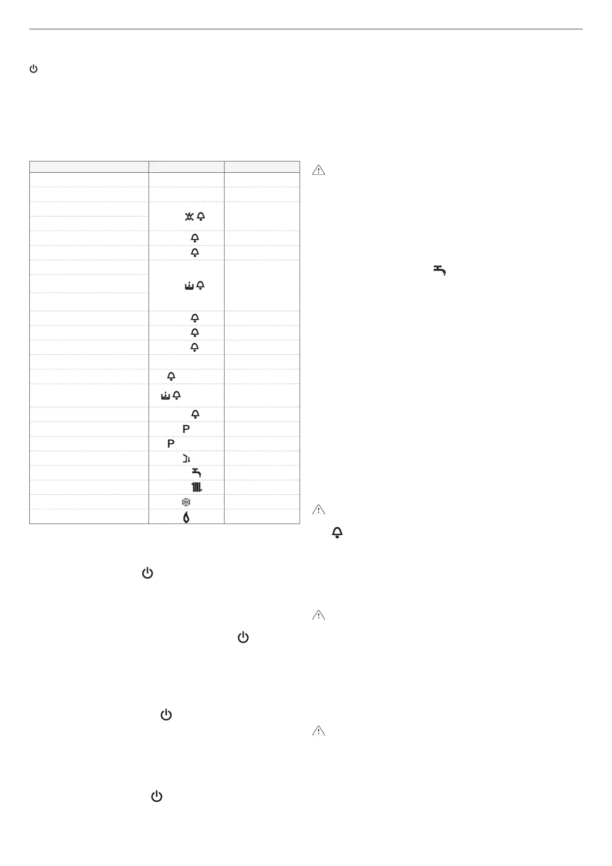
4.4 Operating status and faults
The operating status of the boiler is shown on the digital display, below
is a list of the types of displays.
Boiler status Dis
play
Type of alarm
Stand-by - Signal
OFF status OFF None
ACF alarm lockout module
A01
Denitive lockout
ACF electronics fault alarm
Limit thermostat alarm
A02
Denitive lockout
Air pressure switch alarm
A03
Denitive lockout
Water pressure switch alarm
A04
Denitive lockout
Anti-overow pressure switch
alarm
Reed sensor (if the condense
collector tray kit is installed)
NTC domestic water fault
A06
Signal
NTC heating fault
A07
Temporary stop
Parasite ame
A11
Temporary stop
Temporary, pending ignition 80°C ashing Temporary stop
Air pressure switch intervention
ashing
Temporary stop
Water pressure switch
intervention
ashing
Temporary stop
Calibration
ADJ
Signal
Preheating active function
Signal
Preheating heat request
ashing
Signal
External probe presence
Signal
Domestic water heat request
60°C
Signal
Heat request for heating
80°C
Signal
Antifreeze heat request
Signal
Flame present
Signal
Reset function
To restore operation (reset alarms):
Faults A01-02-03
Turn the function selector to OFF (fig. 34), wait 5-6 seconds, then
turn it to the required position. If the reset attempts do not reactivate the
boiler, contact the Technical Assistance Centre.
Fault A04
- Insufficient water pressure
Check the pressure value indicated by the water gauge:
if it is less than 0.5 bar, turn the function selector to OFF (fig. 34)
and adjust the filling tap until the pressure reaches a value between
1 and 1.5 bar.
Then turn the function selector to the required position.
If these pressure drops occur frequently, contact the Technical
Assistance Centre.
- Anti-overflow pressure switch
Position the mode selector on (OFF), wait for 5-6 seconds and
then turn it to the required position.
If the fault persists, contact the Technical Assistance Centre.
- Full basin (if the condense collector tray kit is installed)
Remove the basin and empty it (following the instructions supplied
with the kit).
Once the operations have been completed, replace the basin.
Turn the function selector to OFF, wait for 5-6 seconds and then
turn it to the required position.
If the fault persists, contact the Technical Assistance Centre.
Fault A06
The boiler functions normally but does not guarantee a constant
domestic hot water temperature, which remains set at around 50°C.
The intervention of the Technical Assistance Centre is necessary.
Fault A07
Request the intervention of the Technical Assistance Centre.
4.5 Adjustments
The boiler is factory-set by the manufacturer.
If it is necessary to adjust it again, for example after extraordinary main-
tenance, after replacement of gas valve or after gas conversion, carry
out the following procedure.
The maximum output adjustment must be carried out in the
sequence indicated exclusively by qualied personnel.
- remove the housing by loosening the xing screws A (g. 36)
- loosen the screw of the pressure test point downstream from the gas
valve by roughly two turns, then connect the pressure gauge
- disconnect the compensation inlet from the air distribution box
4.5.1 Maximum power and minimum domestic hot water ad-
justment
- Turn on a hot water tap to its maximum output on the control panel:
- set the function selector to (summer) (g. 37a)
- turn the domestic hot water temperature selector to its maximum
(g. 37b)
- power the boiler electrically by setting the main system switch to
“ON”
- check the pressure on the pressure gauge is stable, or use a milliam-
meter connected to the modulator to make sure the latter is receiving
the maximum available current (120 mA for G20 and 165 mA for
LPG)
- use a screwdriver to carefully prise the protection cap out of the ad-
justment screws
- using a fork spanner CH10 on the maximum output adjustment nut
to obtain the value indicated in the data table
- disconnect a modulator faston
- wait until the pressure shown on the pressure gauge is stable at
minimum value
- use an Allen spanner to set the red adjustment screw of the DHW
minimum, calibrating it until the pressure gauge shows the value in-
dicated in the data table
- reconnect the modulator faston
- turn off the domestic hot water tap
- carefully ret the protection cap of the adjustment screws.
4.5.2 Minimum and maximum heating electric adjustment
The “electric adjustment” function is activated and deactivated ex-
clusively by the jumper (JP1) (g. 39).
ADJ appears on the display, indicating that the calibration proce-
dure is in progress.
The function can be enabled in the following ways:
- by powering the card with jumper JP1 inserted and the function se-
lector in the winter position, regardless of the possible presence of
other operation requests.
- by inserting jumper JP1, with the function selector in the winter posi-
tion, without any heat request in progress.
By activating the function the burner is ignited through simulation
of heat request in heating.
To perform calibration operations, proceed as follow:
- switch off the boiler
- remove the housing and the terminal board cover, loosening the
screw B (g. 39) to access the card
- insert jumper JP1 (g. 39) to enable the minimum/maximum heating
adjustment functions of the knobs on the control panel.
- make sure the function selector is in the winter position (see para-
graph 4.2).
- power the boiler
Electric card live (230 Volt)
- turn the heating water temperature adjustment knob B (g. 40) until it
reaches the minimum heating value as indicated in the multigas table
- insert jumper JP2 (g. 39)
- turn the DHW temperature adjustment knob C (g. 40) until it reach-
es the maximum heating value as indicated in the multigas table
- remove jumper JP2 to store the maximum heating value
- remove jumper JP1 to store the minimum heating value and to
quit the calibration procedure
- reconnect the compensation inlet to the air distribution box.

 Loading...