CIAO AT
58
CIAO AT
59
[EN]
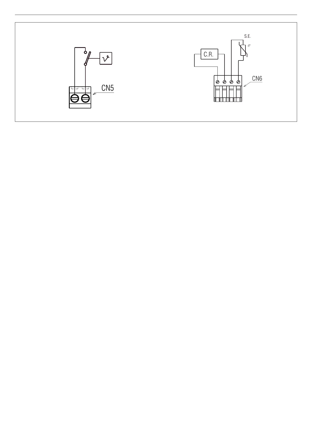
External connections
The AMBIENT THERMOSTAT (TA, 24V DC) is inserted as shown in the
diagram, after removing the U-bolt on the two- ways connector (CN5)
Warning: TA input in safety low voltage.
Low voltage devices should be connected to connector CN6, as shown in
the gure.
C.R.= remote control
S.E. = external probe
g. 6
[FR]
Branchements extérieurs
Le THERMOSTAT AMBIANT (TA, 24Vdc) devra être inséré comme indiqué
sur le schéma après avoir enlevé le cavalier présent sur le conneteur à
deux-voies (CN5)
Attention: Entrée TA en basse tension de sécurité.
Les équipements basse tension devront être branchés comme indiqué sur
la gure sur le connecteur CN6.
C.R. = commande à distance
S.E. = sonde extérieure
[PT]
Conexões externas
O TERMÓSTATO AMBIENTE (TA, 24Vcc) será ativado como indicado pelo
esquema após ter removido a forquilha presente não conectore 2 vias (CN5)
Atenção: Entrada TA em baixa tensão de segurança.
Os utilizadores de baixa tensão serão conectados como indicado na gura
no conector CN6.
C.R.= comando remoto
S.E.= sonda externa
[RO]
Conexiuni externe
TERMOSTATUL (TA, 24Vdc) va introdus astfel cum este indicat în
schemă după îndepărtarea punţii prezente pe conectoar 2 căi (CN5).
Atenţie: Intrare TA de joasă tensiune de siguranţă.
Consumatorii de joasă tensiune vor conectaţi astfel cum este indicat în
gură la conectorul CN6.
C.R.= comandă de la distanţă
S.E.= sondă externă
TA

 Loading...