25
EN
b
As envisaged by current legislation, the boiler is designed to take
in and dispose of ue gas condensate and/or meteoric water con-
densate deriving from the ue gas discharge system using its own
siphon
.
b
If a condensate relaunch pump is installed, check the technical
data (provided by the manufacturer) regarding output, to ensure
it operates correctly
.
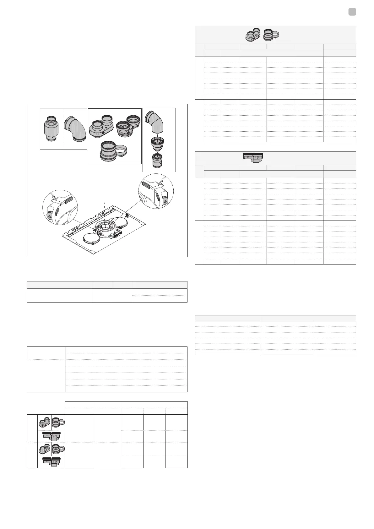
- Position the discharge pipe so that the connection sits fully up against
the ue gases turret of the boiler.
- After positioning it, make sure the 4 notches (A) slip into the groove
(B).
- Fully tighten the screws (C) that hold the two ange locking terminals,
so the bend itself is restrained held in place.
b
For fumes exhaust lengths, please refer to section 8.9 at
page 42.
A
A
C
C
B
B
B
B23P-B53P Ø60-100
Ø80-125
B
B
Ø80-80
b
If the Ø 60-100 to Ø 80-80 splitter kit is used instead of the twin
pipe system, there is a loss in the maximum lengths as shown in
the table
.
Ø 50 Ø 60 Ø 80
Loss of length (m) 0,5 1,2
5,5 for ue gases pipe
7,5 for air pipe
Twin pipes with Ø 80 pipework (Ø50 - Ø60 - Ø80)
Thanks to the boiler characteristics, a Ø80 ue gas exhaust pipe can be
connected to the Ø50 - Ø60 - Ø80 piping ranges.
b
For the pipe, you are advised to make a project calculation in order
to respect the relevant regulations in force.
The table shows the standard congurations allowed
.
Air suction
1 bend 90° Ø 80
4.5m pipe Ø80
Flue gas
discharge
1 bend 90° Ø 80
4.5m pipe Ø80
Reduction from Ø80 to Ø50 from Ø80 to Ø60
Flue base bend 90°, Ø50 or Ø60 or Ø80
For ducting pipe lengths see table
The boilers are factory set to:
CH rpm DHW rpm max length pipes (m)
Ø50 Ø60 Ø80
25C
7.000 8.700
6 19 95
1 9 45
30C
6.900 8.300
4 16 80
0 7 35
Should greater lengths be required, compensate the pressure drop with
an increase in the r.p.m.of the fan, as shown in the adjustments table,
to provide the rated heat input, referring to paragraph “4.9 Adjustments”.
b
The minimum calibration should not be modied.
b
In case of new fan speed adjustment, carry out the CO2 check
procedure as indicated in paragraph “4.8 Combustion analysis”.
Adjustment tables INSIDE CHIMNEY PIPES
twin ue pipe
Fan rotations rpm Pipes Ø50 Pipes Ø60 Pipes Ø80 ∆P at boiler outlet
CH DHW Maximum length (m)
25C
7.000 8.700
6
19 95 180
7.100 8.800
12 *
33 * 165 * 260
7.200 8.900
16 *
39 * 195 * 300
7.300
9.000 19 *
46 * 230 * 342
7.400
9.100 23 *
53 * 265 * 383
7.500
9.200 27 *
61 * 305 * 431
7.600
9.300 29 *
67 * 335 * 465
7.700
9.400 32 *
73 * 365 * 500
30C
6.900
8.300 4 16
80 180
7.100 8.500
8 *
26 * 130 * 260
7.200 8.500
11 *
32 * 160 * 300
7.300 8.700
14 *
38 * 190 * 342
7.400 8.800
17 *
44 * 220 * 383
7.500 8.900
19 *
50 * 250 * 431
7.600 9.000
22 *
56 * 280 * 465
7.700 9.100
25 *
62
*
310 * 500
(*) Maximum length that can be installed ONLY with class H1 discharge pipes.
compact twin ue pipe
Fan rotations rpm Pipes Ø50 Pipes Ø60 Pipes Ø80 ∆P at boiler outlet
CH DHW Maximum length (m)
25C
7.000 8.700
1
9 45 180
7.100 8.800
7 *
23 *
115 *
260
7.200 8.900
11 *
29 *
145 *
300
7.300
9.000 14 *
36 *
180 *
342
7.400
9.100 18 *
43 *
215 *
383
7.500
9.200 22 *
51 *
255 *
431
7.600
9.300 24 *
57 *
285 *
465
7.700
9.400 27 *
63 *
315 *
500
30C
6.900
8.300 0 7
35
190
7.100 8.500
4 *
17* 85 * 256
7.200 8.500
7 *
23 * 115 * 300
7.300 8.700
10 *
29 * 145 * 340
7.400 8.800
13 *
35 * 175 * 380
7.500 8.900
15 *
41 * 205 * 417
7.600 9.000
18 *
47 * 235 * 458
7.700 9.100
21 *
53
*
265 * 500
(*) Maximum length that can be installed ONLY with class H1 discharge pipes.
The Ø50 or Ø60 or Ø80 congurations contain Lab test data. In the event
of installations that dier from the indications in the “standard congu-
rations” and “adjustments” tables, refer to the equivalent linear lengths
below.
b
In any case, the maximum lengths declared in the booklet are gua-
ranteed, and it is essential not to exceed them.
3.9
COMPONENT Linear equivalent in metres Ø80 (m)
Ø 50 Ø 60
Bend 45° 12,3 5
Bend 90° 19,6 8
Extension 0.5m 6,1 2,5
Extension 1.0m 13,5 5,5
Extension 2.0m
29,5 12
Installation on collective ues in positive
pressure
The collective ue is a ue gas exhaust system suitable for collecting
and expelling the combustion products of several appliances installed on
several oors of a building.
The positive pressure collective ues can only be used for type C con-
densing appliances. Therefore the B53P/B23P conguration is forbid-
den. The installation of boilers under collective pressure ues is allowed
exclusively in G20.
The boiler is sized to operate correctly up to a maximum internal pressure
of the ue no higher than the value of 25 Pa. Check that the fan speed
corresponds to what is shown in the “technical data” table.
Make sure that the air intake and exhaust pipes of the combustion prod-
ucts are watertight.
WARNIGS:
b
The appliances connected to a collective pipe must all be of the same
type and have equivalent combustion characteristics.
b
The number of devices connected to a positive pressure collective
pipe is dened by the ue designer.
The boiler is designed to be connected to a collective ue sized to op-
erate in conditions where the static pressure of the collective ue pipe
can exceed the static pressure of the collective air duct of 25 Pa in the
condition in which n-1 boilers work at maximum rated heat input and 1
boiler at the minimum rated heat input allowed by the controls.
 Loading...