Do you have a question about the Beretta EXCLUSIVE BOILER GREEN 30 B.S.I. and is the answer not in the manual?
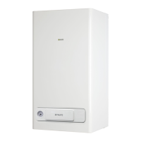
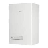
| Model | EXCLUSIVE BOILER GREEN 30 B.S.I. |
|---|---|
| Category | Boiler |
| Manufacturer | Beretta |
| Type | Condensing |
| Power Output | 30 kW |
| Mounting | Wall |
| Fuel Type | Gas |
| Dimensions (H x W x D) | 345 mm |
Key safety precautions for boiler operation and electrical safety.
Installation requirements for Type C sealed chamber boilers.
Installation guidelines for forced open (Type B23P/B53P) configurations.
Details various fume exhaustion and burning air suction configurations.
Installation guidelines for concentric outlets with 60-100mm diameter.
Installation for concentric outlets with 80-125mm diameter using adaptor.
Installation guidelines for twin outlets with 80mm diameter.
Explanation of the functions and commands on the boiler control panel.
Key to understanding the various symbols shown on the boiler display.
Step-by-step instructions for powering on and initiating the boiler.
How to set the desired heating water temperature via the selector.
Setting heating water temperature when using an external sensor.
How to set the desired domestic hot water temperature.
Explanation of normal boiler working and stand-by states.
Instructions for switching off the boiler for short and long periods.
How to use the semi-automatic system to fill the boiler circuit.
How to view operating information and system data using the INFO button.
List of codes and data for technical assistance centre diagnostics.
Procedures for resetting temporary and permanent boiler faults.
How to set and enter the password to access programming parameters.
Steps to change boiler parameters using the control panel selectors.
Verifying correct connection of the external probe to the boiler.
Configure building insulation level for optimal heating delivery.
Setting the maximum and minimum delivery temperatures for heating.
Activating the thermoregulation function using the external probe.
Selecting the heating curve offset based on building and system type.
Configuring heat request based on thermostat or timer connection.
Overview of calibration and service phases for boiler adjustments.
Procedure for setting the correct gas type for boiler operation.
Procedure for setting the boiler's maximum power output.
Setting the maximum speed for the boiler's fan.
Setting the minimum speed for the boiler's fan.
Setting the fan speed for ignition sequences.
Adjusting the boiler's maximum power based on CO2 readings.
Adjusting the boiler's minimum power based on CO2 readings.
Setting the fan speed for slow start ignition.
Adjusting the maximum heating fan speed possibility.
Adjusting the minimum heating fan speed possibility.
Identifies the main operating components of the boiler in English.
Diagram and explanation of the domestic and heating water circuits in English.
Explanation of wiring connections for the boiler in English.
Instructions for connecting thermostats and time clocks in English.
Graph showing residual head for CH system based on capacity in English.



 Loading...