This document provides installation, maintenance, and usage instructions for Bertazzoni fixed hobs with gas or mixed supply.
Function Description:
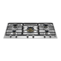
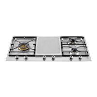
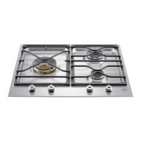
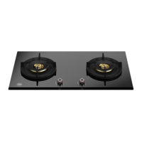
The Bertazzoni hobs are designed for domestic cooking, utilizing gas or a mixed supply. They are not equipped with devices to remove combustion products, requiring proper ventilation of the premises where they are installed. The hobs feature multiple burners, including dual, rapid, and medium burners, each controlled by a dedicated knob. Some models are equipped with a safety device (thermocouple) that requires the knob to be pressed for about 10 seconds after ignition to allow the flame to heat the thermocouple, ensuring the flame remains lit.
Important Technical Specifications:
- Dimensions: (890 mm) (W) x (520 mm) (D).
- Models: PM36500X (Type 'A') and PM365S0X (Type 'B').
- Overhead Clearances: Minimum clearance between the top of the highest burner and a range hood should be at least 650mm. Any other downward-facing combustible surface less than 600mm above the highest burner must be protected. Minimum clearance to any surface is 450mm. Maximum depth for overhead cabinets is 330mm.
- Side Clearances: Specific minimum clearances (L1-L9, B1-B4) are provided in Table n.1, varying by hob model. For example, L1 is 500mm, L2 is 40mm, W is 890mm, D is 520mm, B1 is 40mm, B2 is 152mm, B3 is 40mm, and B4 is 152mm.
- Ventilation: The installation premises must be continuously ventilated with a volume of not less than 25 m³. Permanent openings connected to the outside, with a minimum section of 100 cm², are required for natural air flow.
- Gas Connection: The gas inlet connection is threaded 1/2 gas cylindrical male, in accordance with UNI-ISO 228-1 norms. The appliance is designed for specific gas types and pressures, indicated on a label.
- Electrical Connection: The appliance requires an efficient earth connection. For socket connection, a standard plug appropriate for the charge indicated on the label should be used. Wiring connections are L (phase) = brown, N (neutral) = blue, earth = green-yellow. If connected directly to the supply mains, a disconnection means with contact separation in all poles (overvoltage category III) must be incorporated. The earth wire must be approximately 2 cm longer than phase conductors. The electric cable must not reach temperatures over 75 K.
- Mains Cable Type: H05VV-F 3x0.75 mm2 or H05RR-F 3x0.75mm2.
- Temperature Resistance: The back wall and surrounding surfaces must resist a temperature of 65°C. The glue used for kitchen units must resist temperatures up to 150°C.
- Burner Nozzles: Nozzles can be changed to adapt to different gas types (Natural G20, Butane G30, Propane G31). Table N°2 provides nominal and reduced charge values, as well as nozzle diameters for semi-rapid, rapid, and dual burners. For example, a semi-rapid burner with Natural G20 gas uses a 101 (1/100mm) nozzle diameter, 1.75 Kw nominal charge, and 0.44 Kw reduced charge.
Usage Features:
- Control Knobs: Each burner has a corresponding knob on the control panel, with a diagram indicating the associated burner.
- Manual Ignition: Possible even without power. Turn the knob counterclockwise to the MAXIMUM position (large flame symbol) and place a lit match near the burner.
- Safety Device (Thermocouple) Ignition: Turn the knob counterclockwise to MAXIMUM, press it down to activate spark ignition, and hold for about 10 seconds after ignition to heat the thermocouple.
- Flame Adjustment: Adjust the burner flame size to prevent it from extending beyond the edge of the cooking utensil. Turn the knob to MINIMUM when liquid is boiling.
- Pan Usage: Use suitable pots with flat, thick bottoms (except for wok cooking). Recommended pan diameters are 140-260mm for medium burners, 180-260mm for large burners, and 220-260mm for dual burners. Ensure pan handles are correctly positioned.
- Safety Precautions:
- Keep the appliance area clear of combustible materials, gasoline, and other flammable vapors/liquids.
- Do not store dangerous or flammable materials in cabinets above the appliance.
- Do not use for space heating.
- Avoid aerosol sprays near the appliance during operation.
- Do not leave the appliance unattended when cooking with oil or fat.
- Keep children away from the appliance.
- If gas is smelled, do not light any appliance, touch electrical switches, or use a phone. Immediately call the gas supplier or fire department.
Maintenance Features:
- Qualified Staff: Installation, changes, and maintenance must only be carried out by qualified staff.
- Disconnection: Disconnect the appliance from gas and electric supply before any maintenance work.
- Part Replacement: To replace components (burners, taps, electrical parts), remove the hob from the kitchen unit by releasing fixing hooks, unscrewing burner fixing screws, and electric plate fixing nuts. If taps are replaced, unscrew gas ramp fixing screws and replace the seal.
- Electric Cable Replacement: The electric cable is connected with a type X connection and can be replaced with the same type (H05VV-F 3x0.75 mm2 or H05RR-F 3x0.75mm2). The earth conductor must be about 2 cm longer than phase conductors.
- Nozzle Change: Lift burners, unscrew existing nozzles (using a 7mm adjustable spanner), and replace with nozzles suitable for the new gas supply (refer to Table N°2). Save removed orifices for future use.
- Minimum Flame Regulation: For natural gas burners, turn on the burner to MINIMUM, remove the knob, and use a small screwdriver to turn the gold screw (Fig. 10) on the tap bar until the flame is regulated. Ensure the flame does not go out when quickly changing position from MAXIMUM to MINIMUM. For propane gas, the screw must be fully screwed in clockwise.
- Cleaning:
- Disconnect from power supply before cleaning.
- Use warm soapy water for the work surface, burner heads, enamelled steel pan supports, and burner caps.
- Remove spills immediately with a rag.
- Never use abrasive cleaners or powders.
- Avoid leaving acidic or alkaline substances (vinegar, lemon juice, salt, tomato sauce) on enamelled parts.
- Do not wash enamelled parts while hot.
- For stainless steel parts, use soapy water and dry with a soft cloth; periodically use suitable products to maintain shine.
- Lift burner caps, wash in soapy water, dry thoroughly, and ensure holes are not clogged before replacement.
- Valve Issues: If a valve becomes difficult to open or close, do not force it; immediately contact technical service personnel.
- Leak Test: After installation or service involving main gas parts, perform a leak test using soapy water on gas connections. Do not use fire for leak testing.
This appliance is marked according to European directive 2012/19/EU on Waste Electrical and Electronic Equipment (WEEE), promoting return and recycling.