BEST ACCESS SYSTEMS
Indianapolis, Indiana
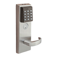
Overview
1 Mark centerlines
Note 1: If the door is a fabricated hollow metal door, determine
whether it is properly reinforced to support the lock. If the door rein-
forcement is not adequate, consult the door manufacturer for informa-
tion on proper reinforcement.
Note 2: The suggested height from the floor to the centerline of the
knob/lever is 38“.
1 Mark the horizontal centerline of the lock on both sides of the door
and on the door’s edge.
2 Mark the vertical centerline of the lock on the door’s edge.
3 Mark the vertical centerline of the lock on both sides of the door as
measured from the vertical centerline on the door’s edge.
4 Mark the horizontal centerline of the strike on the door jamb 3/8“
above the horizontal centerline of the lock.
2 Position template
1 Cut the template along the dotted line and align the horizontal and
vertical arrows to the marked centerlines on the door.
2 Tape the template onto the door.
3 Center punch the drill points.
3 Mortise for lock case and front
Mortise the edge of the door to accommodate the lock case and face
plate.
Figure 1
Figure 2
Vertical
centerline of
cylinder and
knob/lever
Horizontal
centerline of
lock
Horizonal
centerline of
knob/lever
(recommended
height 38“ from
floor)
2 3/4“ backset
Vertical centerline of
door edge and lock front
1 1/2“
3/8“
Centerline
of strike
ecommen
e
door/jam gap
~ 1/8“
Figure 3
Figure 4
Mortise case
Installation Instructions for
V Series 34HV–35HV Locksets
1T61853/Rev – 1852819 ER-7991-1