EasyManua.ls Logo

Best D49MSB Series - User Manual

Best D49MSB Series
44 pages
Print Icon
To Next Page IconTo Next Page
Loading...
Page 1
Models D49M30SB • D49M36SB • D49M48SB
DOWNDRAFT
VENTILATOR
WARNING
READ AND SAVE THESE INSTRUCTIONS
WARNING
TO REDUCE THE RISK OF FIRE, ELECTRIC SHOCK, OR IN-
JURY TO PERSONS, OBSERVE THE FOLLOWING:
1. Use this unit only in the manner intended by the manufacturer.
If you have questions, contact the manufacturer at the address
or telephone number in the warranty.
2. Before servicing or cleaning unit, switch power off at service
panel and lock the service disconnecting means to prevent
power from being switched on accidentally. When the service
disconnecting means cannot be locked, securely fasten a
prominent warning device, such as a tag, to the service panel.
3. Installation work and electrical wiring must be done by a
qualified person(s) in accordance with all applicable codes
and standards, including fire-rated construction codes and
standards.
4. Sufficient air is needed for proper combustion and exhausting
of gases through the flue (chimney) of fuel burning equip-
ment to prevent backdrafting. Follow the heating equipment
manufacturer’s guideline and safety standards such as those
published by the National Fire Protection Association (NFPA),
and the American Society for Heating, Refrigeration and Air
Conditioning Engineers (ASHRAE), and the local code authori-
ties.
5. When cutting or drilling into wall or ceiling, do not damage
electrical wiring and other hidden utilities.
6. Ducted fans must always be vented to the outdoors.
7. To reduce the risk of fire, use only metal ductwork.
8. Do not install this product with the activating switch directly
behind a burner or element. Minimum distance between the
switch and the edge of the burner should be 4 inches.
9. Loose-fitting or hanging clothing should never be worn when
operating this appliance. They may be ignited by burners/
elements on cooktop.
10. Children should not be left alone or unattended in the area
where this appliance is in use.
11. This unit must be grounded.
TO REDUCE THE RISK OF A RANGE TOP GREASE FIRE:
a) Never leave surface units unattended at high settings.
Boilovers cause smoking and greasy spillovers that may
ignite. Heat oils slowly on low or medium settings.
b) Always turn hood ON when cooking at high heat or when
cooking flaming foods.
c) Clean ventilating fans frequently. Grease should not be
allowed to accumulate on fan or filter.
d) Use proper pan size. Always use cookware appropriate
for the size of the surface element.
TO REDUCE THE RISK OF INJURY TO PERSONS IN THE
EVENT OF A RANGE TOP GREASE FIRE, OBSERVE THE
FOLLOWING
a
:
1. SMOTHER FLAMES with a close-fitting lid, cookie sheet, or
metal tray, then turn off the burner. BE CAREFUL TO
PREVENT BURNS. If the flames do not go out immedi-
ately, EVACUATE AND CALL THE FIRE DEPARTMENT.
2. NEVER PICK UP A FLAMING PAN - You may be burned.
3. DO NOT USE WATER, including wet dishcloths or towels - a
violent steam explosion will result.
4. Use an extinguisher ONLY if:
A. You know you have a Class ABC extinguisher, and you
already know how to operate it.
B. The fire is small and contained in the area where it
started.
C. The fire department is being called.
D. You can fight the fire with your back to an exit.
a
Based on “Kitchen Firesafety Tips” published by NFPA.
CAUTION
1. For indoor use only.
2. For general ventilating use only. Do not use to exhaust hazard-
ous or explosive materials and vapors.
3. To avoid motor bearing damage and noisy and/or unbalanced
impellers, keep drywall spray, construction dust, etc. off power
unit.
4. Clean filters and grease-laden surfaces frequently.
5. Do not repair or replace any part of this appliance unless
specifically recommended in this manual. All other servicing
should be done by a qualified technician.
6. Please read specification label on product for further informa-
tion and requirements.
7. To reduce the risk of fire and electric shock, install this downdraft
only with blower models shown below. Other blower models
cannot be substituted. (Blowers sold separately).
Flex Blower Model PF6
Exterior Blower Models EB6, EB9, EB12, or EB15
In-Line Blower Models ILB3, ILB6, ILB9 or ILB11
For use with these blowers
(purchase blowers separately):
Model PF6* - Flex Blower - Interior
Models EB6, EB9*, EB12*, or EB15* - Exterior
Models ILB3, ILB6, ILB9 or ILB11* - In-Line
*
Recommended models
!
INSTALLER:
Save this manual for Electrical
Inspector and Homeowner to use.
Register your product online at: www.BestRangeHoods.com
Question and Answer IconNeed help?

Do you have a question about the Best D49MSB Series and is the answer not in the manual?

Summary

Safety Instructions and Warnings

General Safety Warnings

Safety instructions to reduce fire, electric shock, and injury risks.

Grease Fire Safety

Precautions and actions for preventing and managing range top grease fires.

General Precautions

Important cautions for unit operation, installation, and maintenance.

Planning and Ductwork

Ductwork Planning

Guidance on planning ductwork for various blower and discharge configurations.

Cabinet Preparation and Wiring

Cabinet Cutout Planning

Instructions for planning and cutting cabinet openings for downdraft installation.

Downdraft Preparation

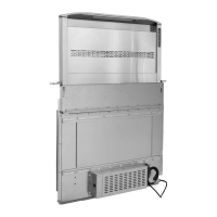
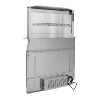
Steps to prepare the downdraft unit for installation, including panel removal.

Wiring Planning

Guidance on planning electrical wiring, circuit requirements, and outlet placement.

Blower and Panel Installation

Remote Blower Discharge Plate

Instructions for attaching the remote discharge plate for Flex or remote blowers.

Remote Electrical Panel Mounting

Steps for mounting the electrical panel remotely using extension cables.

General Support Leg Installation

Instructions for installing upper support brackets and support legs.

Flex Blower Support Leg Attachment

Steps for attaching blower support legs when using the Flex Blower.

Countertop and Ductwork Connections

Countertop Opening Cut

Detailed steps for cutting the countertop opening using a template.

Ductwork Connection for Side;Rear Exhaust

Connecting rectangular ductwork or transitions for side or rear exhaust installations.

Housing Installation

Up Button Cable Connection

Connecting the UP button cable and ground wire to the downdraft housing.

Housing Placement and Routing

Guidance on placing the housing in the cabinet and routing cables correctly.

Support Leg Attachment

Instructions for extending and attaching support legs to the cabinet bottom.

Upper Support Bracket Attachment

Steps for extending and attaching upper support brackets to cabinet sides.

Finishing and Ductwork Installation

Finish Trim Installation

Steps for installing the finish trim, ensuring proper fit and gap with the top door.

Ductwork Installation Steps

Cutting holes, mounting caps, and connecting ductwork for secure and airtight installation.

Electrical Wiring

Flex Blower Wiring

Wiring instructions for Flex Blower, including box mounting and wire connections.

Remote Blower Wiring

Wiring instructions for remote/in-line blowers, including power cable and connections.

Optional Accessories

Remote Control and Seal Kit

Details on optional remote control and gas cooktop seal kit.

Make-Up Air Damper

Function and installation of the make-up air damper for balanced airflow.

Range Trim Kit

Optional kit for free-standing ranges to cover gaps between range and downdraft.

More Optional Accessories and Appliance Installation

Trim Extension and Rough-In Plates

Optional trim extensions and front panel rough-in plates for different configurations.

Ductwork Components

Information on optional ductwork components like elbows and straight sections.

Cooking Appliance Alignment

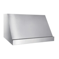
Instructions for aligning the cooking appliance with the downdraft for proper fit.

Use and Care

Cooking Tips

Advice on using the downdraft blower during cooking for optimal performance.

Cleaning Instructions

Detailed steps for cleaning grease filters and the chimney, including safety warnings.

Operation Controls

Task Lighting and Fan Speeds

Operating the 2-level task light and the 4-speed fan control.

Delay Off and Filter Reminder

Using the 10-minute delay off feature and understanding the filter clean reminder.

Chimney Controls and Heat Sentry

Operating the chimney up/down controls and the automatic Heat Sentry function.

Warranty Information

Limited Warranty Details

Details the one-year limited warranty, exclusions, limitations, and remedies.

Service Parts Listing

Part Numbers by Model Width

List of service parts with corresponding part numbers for 30N, 36N, and 48N models.

Service Parts Diagram

Exploded View of Parts

Exploded view diagram illustrating the service parts with corresponding numbers.

Best D49MSB Series Specifications

General IconGeneral
ModelD49MSB
CategoryFan
Voltage220V
Frequency50Hz
MaterialPlastic

Related product manuals