WARRANTY
BESTTEN warrants to the original customer that this productis free
of defects in materials and workmanship for one year from the
purchase date. Within this period, simply contact BESTTEN CARE
with proof of purchase and reason for claim. We will replace the
product for free.
Any product which is subject to misuse or accidental damage is
excluded from this warranty.
support@ibestten.com
1-800-358-6160 (Mon-Fri 9AM-5PM PST)
For more products from BESTTEN, please visit our website
www.ibestten.com.
STEP 1 Turn OFF Power at Breaker or Fuse
INSTALLATION
TROUBLESHOOTING
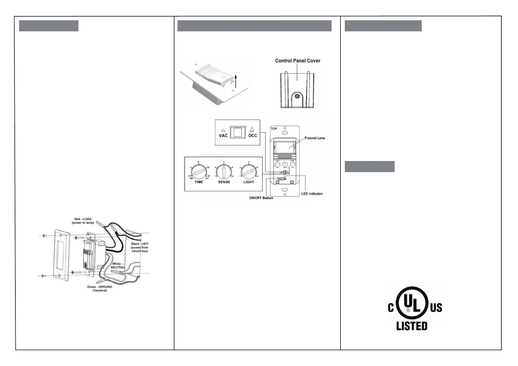
SENSOR ADJUSTMENT & PROGRAMMING
STEP 2 Remove Wallplate and Switch
• Pull off the pre-cut insulation from the sensor wires.
• Make sure that the ends of the wires from the wall box are
straight (cut and strip if necessary).
STEP 3 Prepare Wires:
STEP 4 Wire the Sensor:
Wire in accordance with the appropriate wiring diagram below.
Before installation, please confirm that there is a Neutral Wire
available in the wall box you intend to install this switch. It can
be identified by 2 or more white wires connected together in
the wall box without being connected to a standard switch.
HOT:
identify the Hot Wire in the wall box which has power from the
breaker pannel.This is usually a black wire. Connect it to the black
wire on this switch.
LOAD:
this is usually the other black wire which delivers power to
the light and does not have power. Connect it to the red load wire
on this switch.
NEUTRAL:
connect the white wire on this switch to the existing
Neutral wire.
GROUND:
connect the green wire on this switch to the existing
Green or bare copper wire in the wall box.
STEP 5
Mount the switch into the electrical box and install the
walllplate.
STEP 6 Restore power and test the switch
NOTE:
For sensor to operate, the ON/OFF switch
MUST
be manually pushed
once after installation or a power outage.
Remove the cover located below the sensor lens by inserting a small
screwdriver into the notch located on the bottom of the cover. Gently
pry the screwdriver upward to unlatch the cover.
Time Delay Dial
The time delay dial is marked “TIME”. The adjustment ranges from 15
secs (or Test) to Max 30 Mins.
Sensor Sensitivity Range Dial
The sensitivity adjustment is marked “SENSE”. Adjust the sensitivity
setting to avoid unwanted detection such as hallway traffic or adjacent
movement. Turning the dial counter clockwise will decrease sensitivity
while turning it clockwise will increase it.
Ambient Light Level Dial
This light level dial is marked “LIGHT”. Light setting is used to adjust the
detected ambient light level. The switch will turn on when the light falls
below the set ambient light level. If ambient light level is desired, please
turn the adjustment knob counter clockwise, and push the button to
make sure the sensor start to work. If the ambient light sensor is not
needed, please set it to the maximum setting (Position 5). This will allow
the sensor to turn on and off regardless of ambient light conditions.
Load will not turn ON
Push the ON/OFF button. The load should turn ON. If not:
• Check the light bulb and/or motor switch on the fan mechanism.
• Turn off power to the circuit then check wire connections.
Load will not turn OFF
• Make sure no motion is occurring in the coverage area until the set
time period.
• Hot air currents and heat radiating devices can cause false
detection. Make sure the sensor is at least 6 feet (2 meters) away
from devices that are a significant heat source (e.g., heater, heater
vent, high wattage light bulb).
• Push the ON/OFF button to the OFF. If load does not turn off, turn
off power to the circuit then check wire connections.
Lights turn ON unwantedly or too frequently.
•Sensor may be mounted too closely to an air conditioning or heating
vent. Move the sensor to another location or close the vent.
•Reduce the sensitivity level.
The sensor is only compatible with a single pole circuit.
 Loading...