Do you have a question about the BFT PHOBOS BT A40 and is the answer not in the manual?
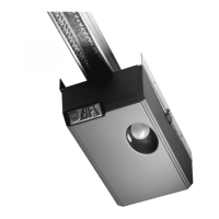
Instructions for securely attaching the system's fittings to the pillar structure.
Guidance on connecting the power supply cable to the automated system.
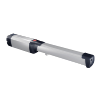
Steps for mounting the motor unit onto the pillar fastening bracket.
Defines the maximum allowable tilt angle for the automated system.
Procedure for fixing the operator unit to the gate leaf for proper function.
Adjusting the mechanism that stops the gate at the fully closed position.
Adjusting the mechanism that stops the gate at the fully open position.
Essential safety guidelines and precautions for installers during system setup.
Critical instructions for safe electrical connections and wiring practices.
Procedures for verifying system functionality and performing regular maintenance.
Guidelines for environmentally responsible disposal and safe dismantling of the system.
Detailed technical data, including power, force, speed, weight, and conditions.
Visual guides and measurements for component positioning and pillar fastening.
Recommendations for leaf stops and instructions for manual system operation.
Information on the necessity and connection of an electric lock for specific gate sizes.
Crucial safety rules for users to prevent injury and damage during operation.
Instructions on how to safely release and manually operate the gate in emergencies.
Information on intended use, manufacturer liability, and product compliance.
| Operating Temperature | -20°C to +55°C |
|---|---|
| Motor Power Supply | 24 V |
| Max. Leaf Length | 4 m |
| Max. Leaf Weight | 500 kg |
| Limit Switch Type | Magnetic |
| Bluetooth Connectivity | No |
| Type | Electromechanical operator for swing gates |
| Power Supply | 230V AC, 50Hz |
| Locking | Mechanical |
| Motor Type | Electromechanical |
| Safety Features | Obstacle detection |