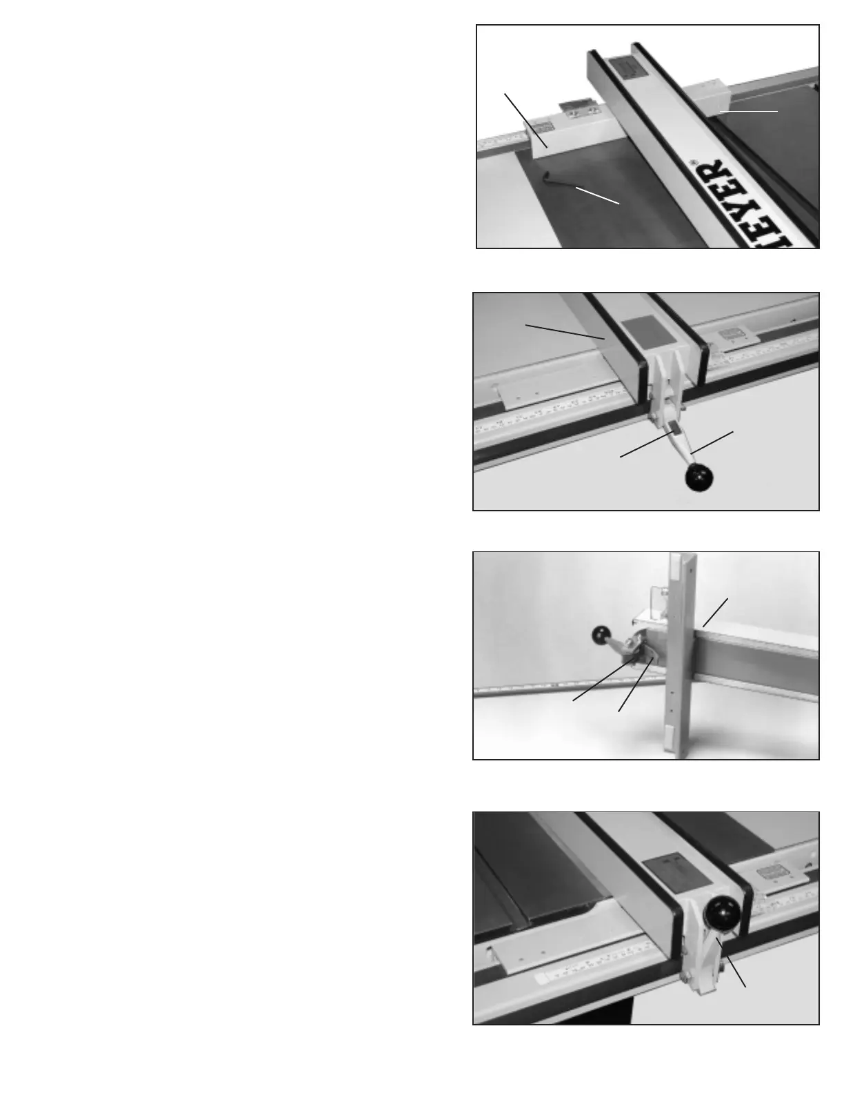
5. When the fence locking handle (B) Fig. 28, is pushed
to the down position, the fence assembly (C) should be
completely clamped to the guide tube. If the fence
assembly (C) is not completely clamped to the guide tube
when the handle is pushed down, as shown, lift up handle
(B) and raise fence off the guide tube as shown in Fig. 27.
Slightly tighten the two adjusting screws (J) and (K) (if the
fence is too loose) or loosen (if the fence is too tight),
using a 3/16” Allen wrench (N), not supplied. NOTE:
Screws (J) and (K) should be tightened or loosend an
equal amount. Replace the fence back on the guide tube
and recheck to see if the fence assembly is completely
tightened to the guide tube with the locking handle (B)
pushed down. Adjust further if necessary.
IMPORTANT: AFTER ADJUSTING THE FENCE
CLAMPING ACTION, RECHECK TO SEE THAT THE
FENCE IS STILL PARALLEL TO THE MITER GAGE
SLOT AND ADJUST AS NECESSARY.
6. When clamping the fence assembly (C) to the guide
tube, make certain the camfoot (P), Fig. 29, is hanging
down and against the locking handle (B), and not caught
on top of the guide tube.
7. To move the fence along the guide tube, simply lift up
the locking handle (B) Fig. 30, as shown, slide the fence
to the desired position on the guide, and push down
locking handle (B) Fig. 28 as shown, to lock in position.
NOTE: A magnet (R) Fig. 28, is provided to hold the handle
in the up position when moving the fence.
10
Fig. 27
Fig. 28
Fig. 29
Fig. 30
B
C
C
P
B
B
R
J
K
N
 Loading...