ASSEMBLY (FOR ALL SAWS)
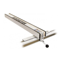
1. Attach knob (A) Fig. 23 to locking handle (B). Knob is
screwed onto threads of locking handle.
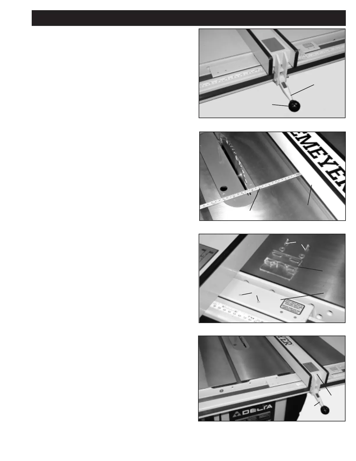
2. Align fence side (C) Fig. 24, with the miter slot on the
table saw and lock fence in position. Using a measuring
tape (D), measure the distance from the saw blade to the
fence side.
3. WITHOUT MOVING THE FENCE, attach hairline
pointer (E), Fig. 25 to fence crossarm (F) using two
#10-32 x 3/8” round head screws and flat washers (G).
Screws go through the slotted holes in the pointer and
into the threaded holes (H) in the crossarm. Using the
measurement from Step 2, align the black line in the
pointer to the same measurement on the guide tube tape
and securely tighten screws.
IMPORTANT: CHECK TO MAKE CERTAIN THAT THE
MITER GAGE SLOTS IN THE SAW TABLE ARE
PARALLEL WITH THE SAW BLADE. CHECK WITH THE
INSTALLATION MANUAL THAT CAME WITH YOUR
SAW FOR INSTRUCTIONS.
4. The fence (C) Fig. 26, must be adjusted so it is parallel
to the miter gage slot. Slide the fence until the bottom
edge is in line with the edge of the miter gage slot as
shown and push down on locking handle (B). Check to
see if the fence (C) is aligned with the miter slot the entire
length of the table. If an adjustment is needed, lift fence
(C) off the guide as shown in Fig. 27. Slightly tighten or
loosen adjusting screws (J) or (K), using a 3/16” Allen
wrench (N), not included. Replace the fence on the guide
tube and check again. Repeat this adjustment until you
are certain the fence is parallel to the miter gage slot.
NOTE: Very little movement of the adjusting screws
is necessary to adjust the fence.
9
Fig. 23
Fig. 24
Fig. 25
Fig. 26
A
B
C
D
E
F
G
H
C
B
 Loading...