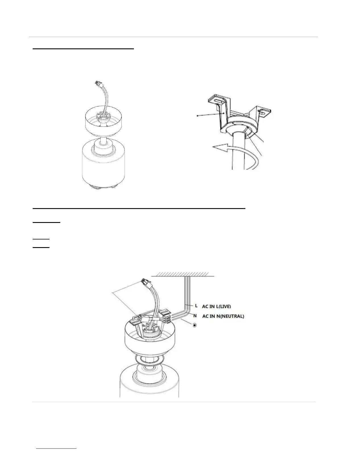
HANGING THE FAN MOTOR ASSEMBLY
Lift the fan assembly onto mounting bracket. Fig. 4
Ensure the notch of the ball joint is positioned on the stopper of the mounting bracket to prevent the fan from
rotating when in operation. Fig. 5
Fig. 4 Fig. 5
PREPARE AND COMPLETE THE ELECTRICAL WIRING — WIRING DIAGRAM (FIG. 6)
WARNING: FOR YOUR SAFETY ALL ELECTRICAL CONNECTIONS MUST BE UNDERTAKEN BY A LICENSED
ELECTRICIAN.
NOTE: AN ADDITIONAL ALL POLE DISCONNECTION SWITCH MUST BE INCLUDED IN THE FIXED WIRING.
NOTE: IF THERE ARE TWO OR MORE DC CEILING FANS INSTALLED IN THE ONE LOCATION, AN ISOLATION
SWITCH IS REQUIRED FOR EACH CEILING FAN. THIS IS REQUIRED WHEN PROGRAMMING THE REMOTE AND
RECEIVER TO PAIR TOGETHER.
Fig. 6