1.Specification and Furetures
3.LED Status
4、Installation of 3G-A
5.Gain Adjust
Specification
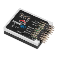
Dimensions: 22mm*31mm
Weight: 7.5g(with cables)
Operating voltage: DC 3.5V-9V
Operating current: 20ma
Maximal angular velocity: 800 degrees/sec
Servo compatibility: 1.52ms analog servo/1.52ms digital servo
Radio compatibility: PPM/PCM/2.4G
Operating Temperature: -15℃--60℃
Features:
2.Function and connection.
Signal Input
AILE IN Signal input for Aileron
ELE Signal input for Elevator
RUD Signal input for Rudder
SW Locking mode switch
Signal Output
AILE OUT Signal output for Aileron
ELEV OUT Signal output for Elevator
RUDD OUT Signal output for Rudder
AILE OUT
ELEV OUT
RUDD OUT
Gyro Gain Adjustment Knob
AIL Gain Adjustment for Aileron
ELE Gain Adjustment for Elevator
RUD Gain Adjustment for Rudder
S1/S2/S3 for Corresponding Model
S1 S2 S3 AIL OUT ELEV OUT
RUDD OUT
Setting 0 0 0 - -
-
Normal
Airplane
Normal Airplane
1 0 0 AIL Servo ELE servo
RUD servo
Flying
Wing(delta)
Flying Wing(delta)
0 1 0 Left wing
servo
Right
wing
servo
RUD servo
V-Tail
V-Tail
0 0 1 AIL servo Left wing
servo
Right wing
servo
Blue flashes rapidly
for 3 secs after
powering on
Initialization is normal,please don’t move
the plane
After initialization,
the blue LED will flash
some times
Flash one time for normal model,two times for
flying wing(delta) and three times for
V-Tail
Initializ
ation
Fast circular flashing
of red LED after
initialization
Initialization failed
Blue LED steady on Normal Mode
Red LED steady on AVCS Mode
Working
Status
Both LEDs Extinguished
Gyro Off
Setting
Mode
Entering into Setting
Mode,the Red LED
flashs slowly
Signal of receiver undetected
Transmitter Setting
Thanks for choosing Bigaole 3G-A Unit.3G-A Unit is a small
and light 3-axis gyro with high performance.3G-A supports 3
types of planes,the normal one,flying wing and V-Tail.With
latest MEMS technology ,3G-A unit provides excellent
stability,flexibility and reliability and make the flight follow the
pilots’ operation more exactly through auto-correcting for
aileron,elevator and rudder.With 3G-A unit,a small bird could fly
as better as a big plane.
Easy switch within AVCS mode,Normal mode and Gyro Off mode
Compact,light,could be used in normal airplane,flying wing and
V-tail,with easy switch change.
Excellently optimized for 3D flight without undermining stability.
Easy set-up,separated adjustment of gain for aileron,elevator and
rudder.
Model Selection
4.1 The 3G-A unit must be installed in a flat and stable platform close to
the center of gravity in your plane,the connecting method refers to the
following diagram:(diagram1)
4.2The 3G-A unit must be installed towards forward in a level platform as
showing in diagram2
Turn on the transmitter and create a new model,set the trims and
sub-trims of all channels to zero,making sure that all mix-function are off.
a.trimming potentiometers AIL,ELE and RUD correspond to the gain
adjustment for those three channels,clockwise to increase and
anti-clockwise to reduce.
b.Gyro Compensation Direction Verification
Locking mode switch
Signal input for Rudder
Signal input for Elevator
Signal output for Rudder
Signal input for Aileron
Signal output for Elevator
Signal output for Aileron
Gain Adjustment for Aileron
Gain Adjustment for Elevator
Gain Adjustment for Rudder
Locking mode switch
Signal input for Rudder
Signal input for Elevator
Signal output for Rudder
Signal input for Aileron
Signal output for Elevator
Signal output for Aileron
Gain Adjustment for Aileron
Gain Adjustment for Elevator
Gain Adjustment for Rudder
Double sided
tape
Airplane
Side View
The center
Direction of forward flight
of the fuselage
Top View
1
2
3
3G-A Instruction Manual
diagram1
diagram2
◆ Connect the gyro,receiver and servo correctly;
◆Choose correct model for your airplane by dialing S1,S2 and S3;
◆Pick up the aircraft around the pitch axis, the roll axis and the yaw axis
to check if the direction of movement of the rudder(control surface) is
correct,otherwise enter into Setting Mode to adjust the compensation
direction of gyro.
◆Move the sticks of aileron,elevator and rudder separately,to see if the
moving direction of rudder(control surface) is correct,otherwise adjust the
normal/reverse of corresponding channel on your transmitter.