Do you have a question about the bihl+Wiedemann AS-i/Modbus Gateway and is the answer not in the manual?
The protection of operating personnel and the system against possible danger is not guaranteed if the control interface unit is not operated in accordance with its intended use.
Safety and correct functioning of the device cannot be guaranteed if any operation other than that described in this operation manual is performed.
The AS-i masters as well as all the AS-i gateways of the are available with two different power supply concepts, "master power supply A" and "master power supply N".
Every AS-i master and all the AS-i gateways in IP65 come with power supply A.
The AS-i masters with master power supply A do not need a voltage supply of their own.
At the bottom of the unit there are 10 terminals for the power supply and the AS-i network.
Do not try to provide the AS-i master with power supply N out of the AS-i power supply of the AS-i circuit.
The AS-i circuits are powered by the master power supply.
The serial interface has been designed as a 9-pin sub-D type socket that is located on the right side of the front plate.
The AS-i/Modbus gateway with RS 485-interface sends and receives on pins 3 and 8 of the sub-D socket.
The AS-i/Modbus gateway with RS 422-interface receives on pins 3 and 8 (“A” and “B”) and sends on pins 4 and 9 (“Y” and “Z”)...
The AS-i/Modbus gateway with RS 232C-interface sends on pin 2 of the sub-D connector ("RxD” signal) and receives on pin 3 ("TxD” signal).
The AS-i/Modbus gateway in IP65 can be connected to Modbus-RS 485 with cage clamp terminals inside of the device.
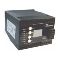
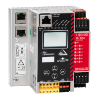
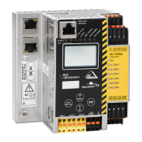
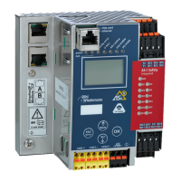
On the front panel of the AS-i/Modbus gateway are seven light-emitting diodes, a two-digit display and two push buttons.
The master's power supply is sufficient. Serial interface communication active via the serial interface.
Switching of the displays and push buttons between the two AS-i circuits.
This list contains entries of all AS-i slaves which were responsible for at least one configuration error since powering up the AS-i master or reading the list.
The AS-i master with advanced diagnostics has an error counter for each AS-i slave, which is increased every time there is a corrupted AS-i telegram.
The AS-i masters with advanced diagnostics offer the possibility to put themselves into the off-line Phase when a configuration error on the AS-Interface occurs.
In protected mode the displays of the double Masters are switched over from AS-i circuit 1 to AS-i circuit 2 in a measure of 2 seconds.
After powering on, all segments of the figure display and all LEDs light up for approximately one second (self-test).
The configuration mode serves to configure the AS-i circuit.
In contrast with the configuration mode in the protected mode there is only data exchange between the AS-i master and the projected AS-i slaves.
You leave the configuration mode by pressing the “mode” button.
As long as there is no configuration error, the numeric display is turned off while in protected operating mode.
AS-i can be put into operation in a very comfortable manner by using the Windows software AS-i Control Tools.
In configuration mode, the addresses of all detected slaves are displayed one after the other.
In configuration mode, the addresses of all recognized slaves are displayed one after the other.
Programming the Address in Case of Configuration Errors
One of AS-i's great advantages is the automatic address assignment.
If several slaves fail, they cannot be replaced automatically by the AS-i master.
The addressing of the AS-i/Modbus gateway as a Modbus node can only be done on the gateway.
The system displays error codes for error messages that do not point to faulty assignments on the AS-i circuit.
When transferring data via the AS-i master's serial interface, RTU-coding (remote terminal unit) is used.
Telegrams from the Modbus-master (query-messages) and answers of the Modbus-slave have the same structure.
The following functions are supported:
This function allows to read the discrete outputs.
This function allows to read discrete inputs.
Parallel to the discrete in and outputs Modbus also supplies registers with word-wide access.
This function allows to access the value of read-only-registers.
Function for reading and writing of one single output.
Function for writing one read/write-register.
Function for setting of several discrete outputs.
Function for setting of several read/write-registers.
This function is not supported.
All execution control-functions in the AS-i/Modbus gateway are initiated via writing specified registers or outputs.
This function is a Modbus service function.
This function is used to read the name and version of AS-i/Modbus gateway:
This function is used to write the Control programs for AS-i Control (download).
This function is used to read back the Control programs for AS-i Control (upload).
The discrete outputs of a Modbus slave can be read by function 1 and manipulated by function 5 and 15.
The discrete inputs of a Modbus slave can be read by function 2.
The read/write-registers of a Modbus slave can be read by function 3 and manipulated by the function 6 and 16.
The read-only registers of a Modbus slave can be accessed by function 4.
| Category | Gateway |
|---|---|
| Protocol | AS-i, Modbus |
| Modbus Slave | Yes |
| Power Supply | 24 V DC |
| AS-i Power Supply | 30 V DC |
| Mounting | DIN rail |
| Protection Class | IP20 |
| AS-i Master | Yes |
| Operating Temperature | -25...70 °C |
| Storage Temperature | -25…85 °C |