Do you have a question about the BikeYoke Divine and is the answer not in the manual?
This is a high performance product. Please read instructions and consult authorized service centers for maintenance.
Only qualified technicians should service the seatpost. Improper use can cause damage or injury.
Read instructions carefully and install your DIVINE dropper post. Refer to website for detailed videos.
Do not drill or modify your frame. This voids warranties and can lead to serious injury or death.
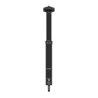
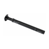
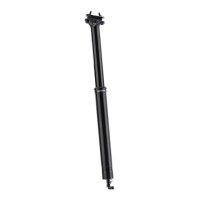
Check frame compatibility (30.9mm or 31.6mm) and ensure proper fit to prevent slippage or damage.
Do not modify your frame; this voids warranties and can lead to serious injury or death.
Ensure the seat tube is clean and free of debris for proper installation and seatpost function.
Use suitable grease on the lower tube to prevent corrosion; use friction paste only if needed.
Seatpost must cover the minimum insertion line to avoid damage, loss of control, injury, or death.
Tighten the seat collar to a maximum torque of 5Nm to ensure proper function without over-tightening.
There is only one correct position for seatpost direction and saddle clamp orientation.
Temporarily install the remote lever on the handlebar to determine the correct cable length.
Install elbow noodle, barrel adjuster, and insert cable housing into the remote lever.
Install the remote via snap-on clamp to the handlebar with a torque of 1-2Nm.
Details on installing I-Spec B and I-Spec II adapters for remote lever mounting.
Route cable housing through the frame, ensuring it's long enough to not impede steering.
Do not permanently affix housing; it needs to be free to move for later adjustments.
Mark the cable housing at the seat collar as it protrudes from the seat tube.
Cut the housing to the marked length, adding 90mm for maximum extension, using proper cutters.
Install the ferrule on the free end of the cable housing, pushing it completely onto the housing.
Feed the inner wire through the remote lever, elbow noodle, and cable housing.
Slide the open barrel nut over the inner cable before connecting.
Hold housing with ferrule, find correct position for barrel nut using gauge, then tighten nut.
Cut inner cable flush with barrel nut, secure with locking cable end using hex keys.
Insert the seatpost into your seattube, being careful not to pull the ferrule out of the cable stop.
Never extend post higher than minimum insertion mark to prevent stress and failure, injury or death.
Ensure no objects like pivot points or bent tubes are inside the seattube that could interfere.
Identify and prepare saddle head clamp bolts, barrel nuts, and floating clamps for installation.
Place saddle rails between upper and lower clamps, resting in the channel provided by the lower clamp.
Tighten head clamp bolts alternately to achieve desired angle, then evenly to 7 Nm.
Adjust air pressure between 250psi and 350psi to customize overload threshold and return speed.
Wear safety gear, hold post upright, and only adjust with fully extended post to prevent injury or fluid leakage.
Push trigger and apply weight to lower; unweight and release trigger to raise saddle.
Clean seatpost with warm water and a clean cloth after every ride, avoiding water entry into the frame.
Check seatpost security, torque, lever action, cable tension, and inspect for damage before riding.
Perform routine maintenance, clean and lubricate internally every 6 months or as needed based on conditions.
Minor vertical movement (up to 1-3mm) under load is normal due to component deformation.
Check linkage for dirt/lubrication, verify air pressure, or ensure valve core is tight.
Check seat collar torque, foam ring condition, and ensure no excess grease is hindering movement.
Regular service by suspension professionals is recommended. Perform safety checks before each ride.
Clean post, check clamp, lever, cable, and inspect for damage or play.
Clean post, ensure frame interior is dry, and store bike in a dry place.
Perform lower tube service every 100 hours of use for wear inspection of the cartridge shaft.
Perform cartridge rebuild only for persistent symptoms not resolved by lower tube service.
| Diameter | 30.9 mm, 31.6 mm, 34.9 mm |
|---|---|
| Material | Aluminum |
| Actuation | Cable |
| Category | Dropper Seatpost |
| Saddle Rail Compatibility | 7x7 mm, 7x9 mm |
| Color | Black |
| Travel | 125mm, 160mm |