Do you have a question about the Bilanciai DD1010 FLYNET and is the answer not in the manual?
Introduces manual purpose, scope, user responsibilities, and safety guidelines.
Lists supplied documentation: Quick Start, Use/Maintenance/Installation Manual, Application Manual.
Explains danger, attention, and warning symbols used throughout the manual for safety.
Defines technical terms and abbreviations found in the manual for clarity.
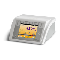
Provides a general overview of the DD1010 FLYNET indicator's features, capabilities, and design.
Defines terminology specific to different indicator models mentioned in the manual.
Details the indicator's technical specifications, including power supply, scale compatibility, and environmental ratings.
Refers to the Declaration of Conformity document, typically found in the Quick Start manual.
Specifies the physical dimensions and weight of the indicator for different versions.
Lists forbidden uses of the indicator to ensure safe operation and prevent equipment damage or injury.
States that the indicator's use must comply with the regulations in force in the country of operation.
Provides essential guidelines for safe and proper operation, maintenance, and connection of the indicator.
General instructions for indoor installation, ensuring stability and protection from direct light.
Details crucial checks and wiring diagrams for safely connecting the indicator to the electrical mains.
Explains the procedure and wiring diagrams for connecting the indicator to various weighing platforms.
Covers configuration and wiring for serial ports like COM4, COM6/7, RS232, and RS422.
Describes the function and operation of the power button for switching the indicator on and off.
Explains that user commands are primarily sent to the indicator via its touch screen interface.
Details how to connect external USB keyboards and mice as control devices for the indicator.
Overview of setting hardware components and system services through functional groups.
Configuration options for system settings, including Metrology, Serial Ports, and Error Notification.
Explains the use of different card types for reader interfacing and their specific configurations.
Details enabling network printing and PDF file generation using unique activation codes.
Covers various data transmission configurations: MPP, Network, Serial, and Field bus.
Explains how to activate optional services like MPP, PDF printer, Network printer, and Axis weighing.
Allows selection of a background colour and theme for the indicator's interface.
Describes how to customize and manage shortcut keys for quick access to software functions.
Explains how to temporarily deactivate the indicator's screen and put it into a low-power standby mode.
Details the use of access passwords to limit setting and deletion of sensitive data by unauthorized personnel.
Describes how to manage and display errors related to Scale and Printer functions.
Explains how the indicator can share its archives with external sources like PCs or other indicators.
Step-by-step procedure for connecting and configuring an external printer to the indicator.
Step-by-step procedure for connecting and configuring a reader for card input and data association.
Procedure for adding network or PDF printers and testing their functionality.
Instructions on how to test serial and network data string transmissions via a PC.
Instructions for installing optional expansion cards into the indicator's slots.
Describes various optional cards including sound, I/O, and analogue output cards.
Lists common indicator problems, their causes, and remedies for troubleshooting.
Details common scale errors, their causes, and remedies, including overload and underload conditions.
Details accessing metrological parameters via calibration button for connector versions.
Details accessing metrological parameters via calibration button for cable gland versions.
Step-by-step guide for performing internal scale sampling procedures.
Procedure for disassembling the support structure on stainless steel indicator models.
Instructions for opening the plastic version of the indicator housing to access internal components.
Instructions for opening the stainless steel version of the indicator housing to access internal components.
Steps for disassembling the front panel and display assembly on the plastic indicator version.
Steps for disassembling the front panel and display assembly on the stainless steel indicator version.
Instructions for removing the indicator's power supply unit on stainless steel versions with cable glands.
Steps for disassembling the power supply unit for scales in the plastic indicator version.
Steps for disassembling the power supply unit for scales in the stainless steel indicator version.
Procedures for removing the lithium battery in the plastic indicator version.
Procedures for removing the lithium battery in the stainless steel indicator version with connectors.
Procedures for removing the lithium battery in the stainless steel indicator version with cable glands.
Specific steps for disassembling weighing cell and power supply unit in stainless steel versions with cable glands.
Instructions for removing the CPU module from the motherboard in the plastic indicator version.
Instructions for removing the CPU module from the motherboard in stainless steel versions.
Steps for disassembling digital scale input cards in the plastic indicator version.
Steps for disassembling digital scale input cards in stainless steel versions with connectors.
Steps for disassembling digital scale input cards in stainless steel versions with cable glands.
Instructions for disassembling analogue scale input cards in the plastic indicator version.
Instructions for disassembling analogue scale input cards in stainless steel versions with connectors.
Instructions for disassembling analogue scale input cards in stainless steel versions with cable glands.
Procedures for removing serial expansion cards in the plastic indicator version.
Procedures for removing serial expansion cards in stainless steel versions with connectors.
Procedures for removing serial expansion cards in stainless steel versions with cable glands.
Steps for disassembling the HDMI expansion port in the plastic indicator version.
Steps for disassembling the HDMI expansion port in stainless steel versions with connectors.
Instructions for disassembling the motherboard from the plastic indicator version.
Instructions for disassembling the motherboard from stainless steel versions with connectors.
Instructions for disassembling the motherboard from stainless steel versions with cable glands.
Guidance on connecting peripheral devices to the indicator's serial and USB ports.
| Brand | Bilanciai |
|---|---|
| Model | DD1010 FLYNET |
| Category | Accessories |
| Language | English |