EasyManua.ls Logo

BilJax Pro-Jax Utility Scaffold User Manual

BilJax Pro-Jax Utility Scaffold
4 pages
To Next Page IconTo Next Page
Page #1 background imageLoading...
Page #1 background image
- Page 4 -
WARNING
• Bothsidebracesmustbepositionedatthesameheightontheframessothatplatformis
level.
• Besureall4Saf-T-Lok
®
pins are fully engaged in holes of end frames.
• Besureall4Saf-T-Loksareinthelockedposition.
STEP TWOAttach second side brace B to both end frames A following the same Step One
sequence.
STEP ONEAttach side brace B to two end frames A by
following this sequence:
- Pull Saf-T-Lok
®
pin at each end of side brace to the
disengaged position. (see decal)
- While holding lock pin in disengaged position, place U-
Channel on each end of side brace B around leg of end
frame A at desired platform height.
- Release lock pin and be sure that pin fully engages into
hole in end frame leg.
- Push in and rotate Saf-T-Lok
®
counter clockwise until U-
shaped end clears the brace locking pin support bracket
as shown (LOCKED).
- To release, push in and rotate Saf-T-Lok
®
clockwise until
U-shaped end unseats from around the brace locking pin
support bracket as shown (UNLOCKED).
For proper assembly, your basic Pro-Jax Utility Scaffold
must be comprised of 13 individual parts (plus guard
rail panels when required).
Letter Part Qty.
A End Frame 2
B Side Brace 2
C Platform 1
D 5” Caster 4
E 2” Snap Pin 4
C
B
A
B
A
E
D
ASSEMBLY INSTRUCTIONS
BUILDING A ONE FRAME HIGH SCAFFOLD
0202-0506
CTO
WARNING
L
Patents Pending
FAILURE TO FOLLOW THESE INSTRUCTIONS MAY RESULT IN
PLATFORM COLLAPSE CAUSING SERIOUS INJURY OR DEATH.


Do not use in this position
Work position
1. Check to be sure brace locking pin is fully
engaged into frame leg.
2. Push in and rotate Saf-T-Lok
TM
counter
clockwise until U-shaped end clears the
brace locking pin support bracket as
shown (LOCKED).
3. To release, push in and rotate Saf-T-Lok
TM
clockwise until U-shaped end unseats from
around the brace locking pin support
bracket as shown (UNLOCKED).
© Bil-Jax, Inc. 2004
Question and Answer IconNeed help?

Do you have a question about the BilJax Pro-Jax Utility Scaffold and is the answer not in the manual?

BilJax Pro-Jax Utility Scaffold Specifications

General IconGeneral
MaterialSteel
Weight Capacity1000 lbs
Width29 inches
Adjustable HeightYes
Length6 ft
Platform Length6 ft
Weight120 lbs
Caster Type5-inch swivel casters with brakes

Summary

Building a One Frame High Scaffold

Step One: Attach Side Brace

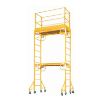
Attach side brace B to two end frames A using Saf-T-Lok pins.

Step Two: Attach Second Side Brace

Attach the second side brace B to both end frames A following the same sequence.

Warning: Brace and Pin Engagement

Ensure side braces are level and Saf-T-Lok pins are fully engaged and locked.

Step Three: Install Platform

Install platform C on side braces B, ensuring it is fully seated.

Step Four: Rotate Platform Clips

Rotate the platform clips into the engaged position for security.

Step Five: Install Casters

Install four casters D into end frame legs and secure with snap pins, setting brakes.

Step Six: Install Guard Railing

Install guard railing as recommended for heights over 4 ft. or required for 10 ft. plus.

Warning: Guard Rail and Access Safety

Ensure guard rail gate swings inward; recheck pins and platform seating before access.

Stacking Pro-Jax Units for Additional Height

General Requirements for Stacking

Scaffolds must be restrained from tipping; outriggers are required for units over 1 frame high.

Building a Two Frame High Scaffold

Instructions for building a two-frame high scaffold using 18" outriggers.

Step Three: Clamp Outrigger

Clamp outrigger to end frame at a 90° angle, ensuring it is flush and casters are on surface.

Step Four: Add Second Scaffold Level

Stack a second end frame over insert pins in the base unit end frames.

Step Five: Install Additional Components

Install side braces, platform, and guard railing per one-frame instructions.

Building a Three Frame High Scaffold

General Requirements for Three Frames

Use 24" wide outriggers for scaffold heights over 11' 6".

Step Two: Install Outrigger Casters

Install casters into all four wide outriggers and secure with snap pins, setting brakes.

Step Three: Clamp Outriggers

Clamp outriggers to end frame with a two-piece clamp, ensuring flush fit and surface contact.

Step Four: Add Scaffold Levels

Add end frames, side braces, platforms, and guard railing per previous instructions.

Warning: Minimum Bracing

Ensure a minimum of two evenly spaced side braces per level to prevent collapse.