created: 04.16.19 E4-WM5-Y630A00_2 Page 19 of 22 latest revision: 09.29.20
Hose Clamp Installation Procedure (both sides)
KK.
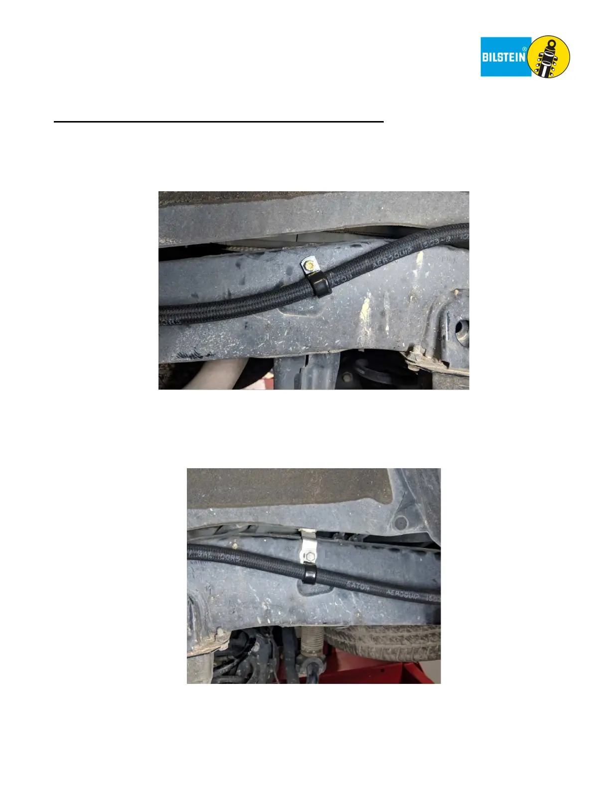
Place the Loop Clamp (BOM item #17) around the hose as shown below. If the hole is threaded, apply non-
permanent thread locker to one of the Flange Head Cap Screws (BOM item #15) and use a 13mm wrench to mount
the hose to the frame. If a Threaded Insert was installed, apply non-permanent thread locker to one of the Hex Head
Cap Screws (BOM item #16) and use a 7/16” wrench to mount the hose to the frame.
Torque either Cap Screw to 14 ft-lb (19 Nm).
Right side depicted. Left side is a mirror image, except for KDSS models.
Note: On the left side of KDSS models there is a Flange Head Cap Screw already present. Remove the screw, apply
non-permanent thread locker, and use it to install the Loop Clamp as shown below.
Torque Flange Head Cap Screw to 14 ft-lb (19 Nm)
LL.
Re-install the plastic panels that were removed in steps K-N (if applicable).
MM.
With the vehicle back on the ground, tighten the OE lower shock bolt/washer that was installed in step F.
Torque OE lower shock bolt to factory specifications. This completes the installation.
 Loading...