925-0270 Rev G 10
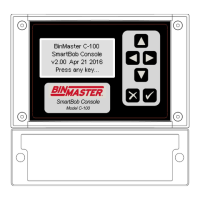
3.2.2 SB-485 for SmartBob Network
The SB-485 connection (CN7) is a three wire terminal block located near the center of the printed circuit
board and is for connection to the SmartBob RS-485 network. Two terminal screws marked + and –
should be connected to the positive and negative wires of the SmartBob network cable. The third
terminal screw marked SH should be connected to the shield of the SmartBob network cable. Do NOT
connect the shield to earth.
All three connections at this terminal block are required in order to properly communicate to any
SmartBob sensors.
A good quality twisted-pair shielded cable should be used for the SmartBob network. The cable should
connect to each device on the SmartBob network in a daisy-chain fashion. Branch lines or splits are not
recommended. The maximum length of the cable should be 4,000 feet or 1,220 meters.
The C-100 SmartBob control console has permanent biasing resistors for the SmartBob network, so
remove or un-switch any other bias resistors on all other devices connected to this network.
Devices located at the ends of the SmartBob network must be properly terminated. For the two devices
located at the ends, switch in their NTR or termination resistor. The C-100 SmartBob control console can
be located anywhere along the SmartBob network and has a software menu for switching it’s termination
in or out of circuit.
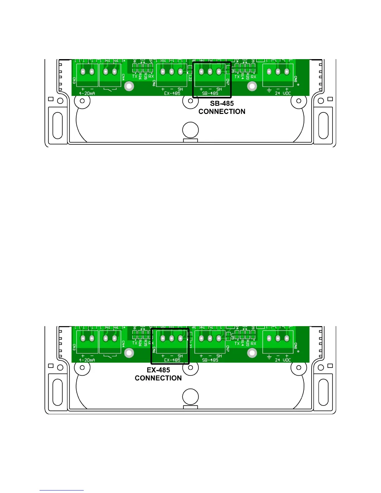
3.2.3 EX-485 for Expansion
The EX-485 connection (CN6) is a three wire terminal block located near the center of the printed circuit
board and is for connection to the Expansion RS-485 network. Two terminal screws marked + and –
should be connected to the positive and negative wires of the RS-485 network cable. The third terminal