6
LVP180914 Rev. D
www.bindicator.com
The LP II unit must be located at the position where level indication is desired. The unit may be mounted through the top
or side wall of the vessel. To ensure reliable operation, observe the following guidelines when choosing the mounting
location.
If using a remote unit, remote turtle cannot be mounted more than 50 feet (15m) away from the probe.
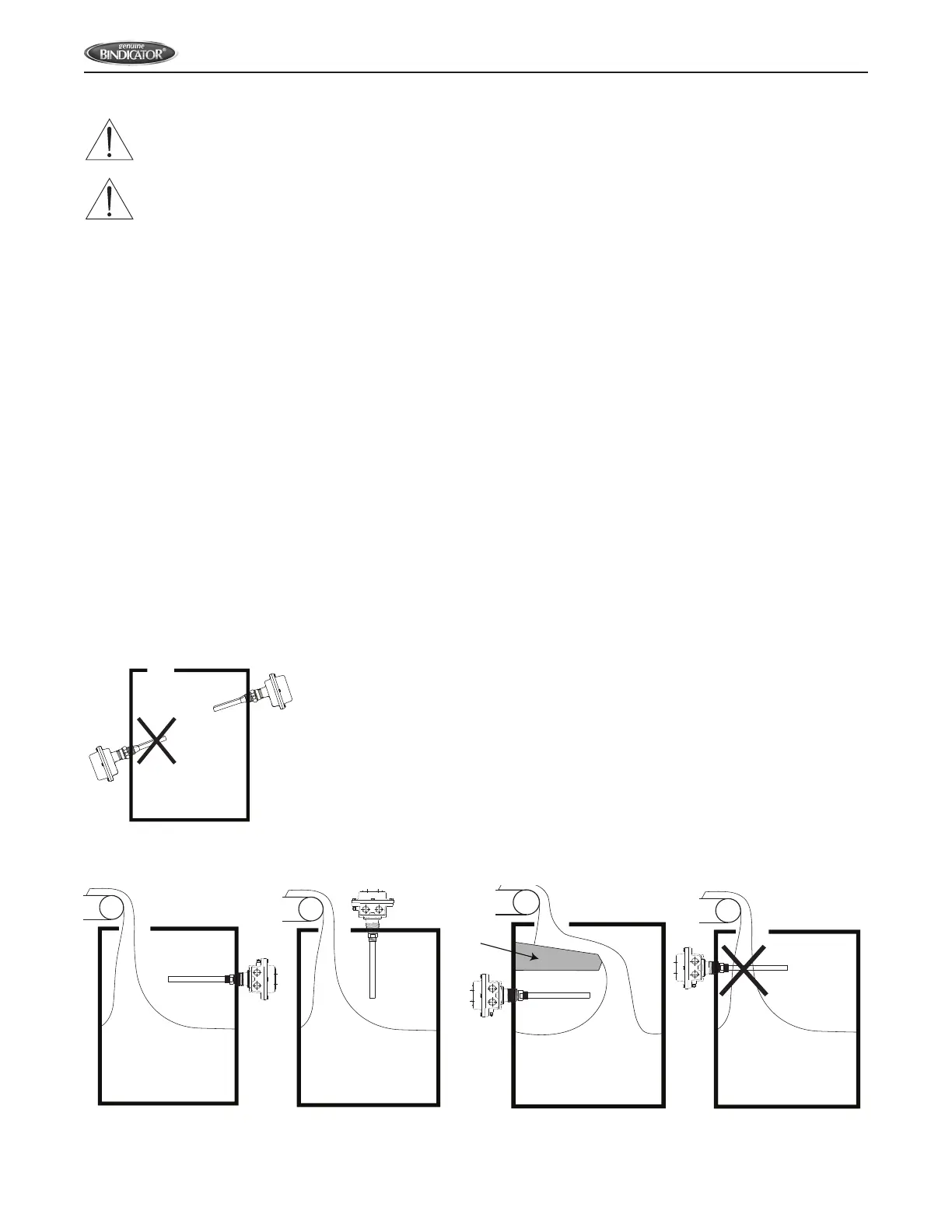
DO NOT mount the unit in an area where the rod can contact the vessel.
The assembly must be horizontal or pointing downward. DO NOT mount the rod pointing upward. If the unit is to be
used with powders, it should be installed vertically, or at a downward angle that exceeds the angle of repose to
reduce material build-up (see gure 1).
Figure 1. Mounting Orientation
Do not mount the rod directly in the ow of material. If necessary, use a bae to protect the rod from falling material. The
bae should be placed 6 to 8 inches (15 to 20 cm) above the rod so that material will not become packed between the
rod and the bae (see gure 2).
Figure 2. Mounting In Relation To Flow of Material
YES
CAUTION: THE MAXIMUM ALLOWABLE DOWNWARD FORCE ON THE ROD IS 700 IN. LBS.
CAUTION: PROPER AND SAFE OPERATION REQUIRES THE UNIT TO BE SECURELY MOUNTED TO THE VESSEL AND
WRENCH TIGHTENED. THE COVER MUST BE PROPERLY INSTALLED WHEN POWER IS SUPPLIED.