17
www.bindicator.com
LVP180914 Rev. D
SENSITIVITY SETTINGS STANDARD MODEL
There are two (2) dierent sensitivity ranges on the LP II that can be selected using SW1 Position 4. The unit is factory set
for the lowest sensitivity. The table below is for illustration purposes, of a vertically mounted unit only, and results will
vary depending on material properties and conditions.
SW1 Position 4 Sensitivity Bulk Density (lbs/ft
3
)
OFF High 6
ON Low ≥ 9
SENSITIVITY SETTINGS ADVANCED MODEL
The LP II provides three (3) levels of sensitivity which are selected using SW3 as shown in the table below. The unit is
factory set for the lowest sensitivity. The table below is for illustration purposes, of a vertically mounted unit only, and
results will vary depending on material properties and conditions.
SW3 Sensitivity Bulk Density (lbs/ft
3
)
0 High 3
1 Medium 6
2-7 Low ≥9
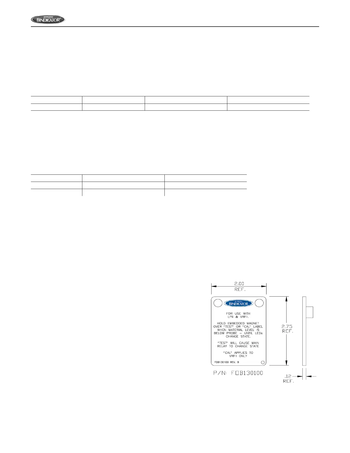
TEST ADVANCED MODEL
The LP II provides a means for self-test using the magnetic FOB provided with the unit. When the unit is not in material
(rod vibrating) place and hold the FOB over the “TEST” label on the cover. If the unit is functioning properly, the alarm LED
and main relay will change the state as shown below. When the test is completed and results veried, simply move the
FOB away from the unit.
HIGH FAILSAFE:
• Main relay de-energizes
• Red ALARM LED is on
LOW FAILSAFE
• Main relay energizes
• Red ALARM LED is o
Figure 14: Magnetic FOB