11
www.bindicator.com
TDR180003 Rev. I
POWER SUPPLY REQUIREMENTS
• 12 to 36 VDC
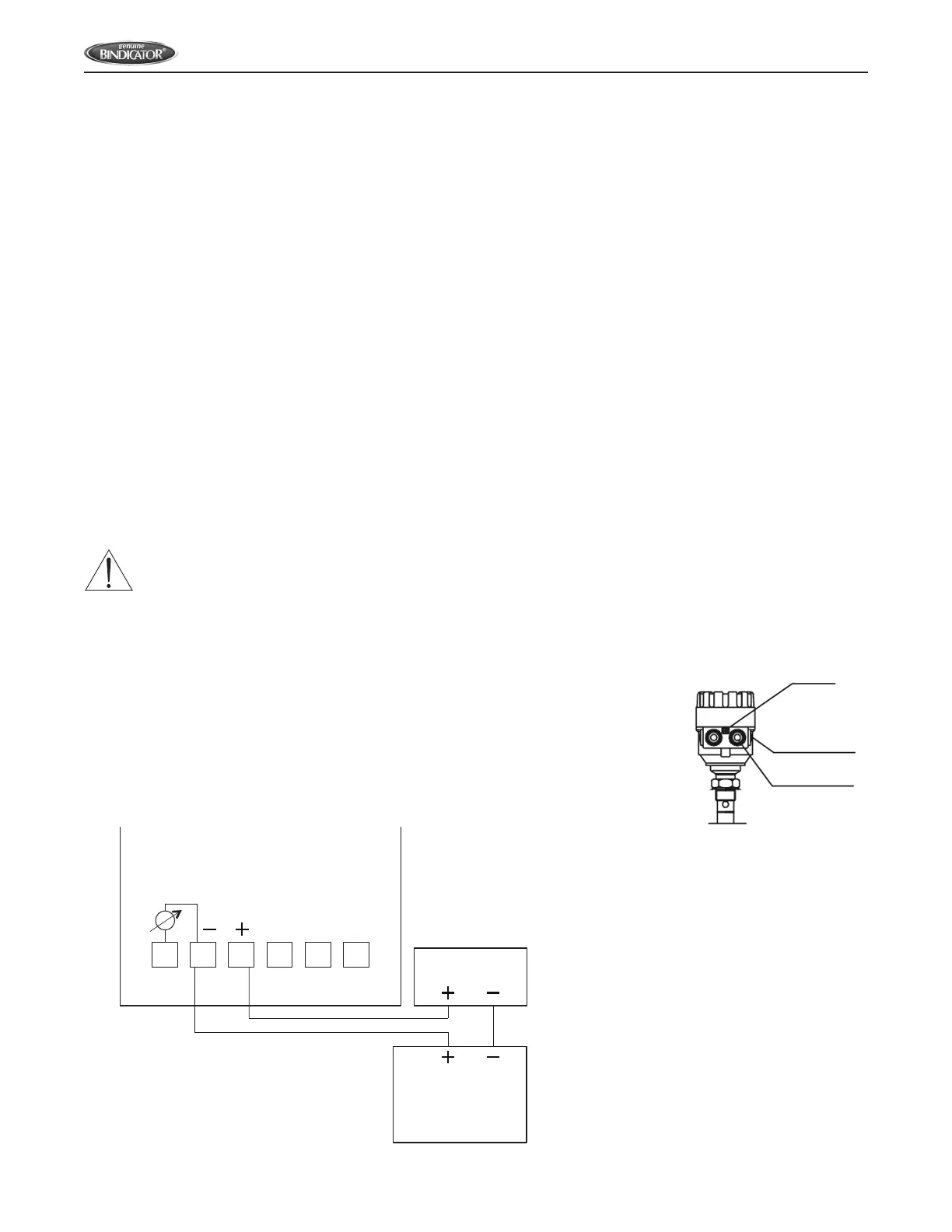
WIRING TDR TO POWER SUPPLY
1. Turn off all power to unit.
2. Detach the cover of the unit.
3. Guide the cable into the housing through the cable gland
4. Remove a 0.16 in (4 mm) length of insulation from the wires and cut away the free part of the shielding.
5. Connect the wires of the current loop to terminals 2 and 3 (any polarity). See Figure 1.
6. Pull back the cable until 0.39 in (10 mm) of length remains in the housing behind the cable gland.
7. Tighten the cable gland using a wrench.
8. Check the connection of wires and the tightness of the cable gland.
9. Properly ground the unit. Screw type terminal on the housing, maximum cable cross-section: 0.006 in
2
(4
mm
2
). Grounding resistance R < 1 ohm. The shielding of the signal cable should be grounded at the control
room. Avoid coupling of electromagnetic noises and place the signal cable away from power-current cables.
WARNING: UNIT HOUSING MUST BE GROUNDED FOR PROPER FUNCTION.
10. Return power to the unit.
11. If unit has been programmed by the company, it is now ready to begin taking
readings. If unit needs to be reprogrammed for the vessel, proceed to the Set Up
Section.
Figure 1: Basic 24 V Wiring – TDR to Power Supply
EP
NPT
1
/
2
”
M20 x 1.5
1 2 3 4 5 6
4-20 mA
mV Test
24 VDC
Power Supply
PRD1000 and PRD6000
Display
PLC Input or
other 4-20 mA Device