4
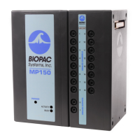
Transducer Cable –RF panel to patient
The Transducer cable (see figure 3) is suitable to use inside the MRI chamber room. It supports one to
five subject or transducer electrical connections and is 8 meters long. The cable incorporates a plastic
housed DSUB9 Male connector to panel mount with the chamber room exposed female connector of
the MRI filter.
Figure 3.
Transducer Cable in MRI Room
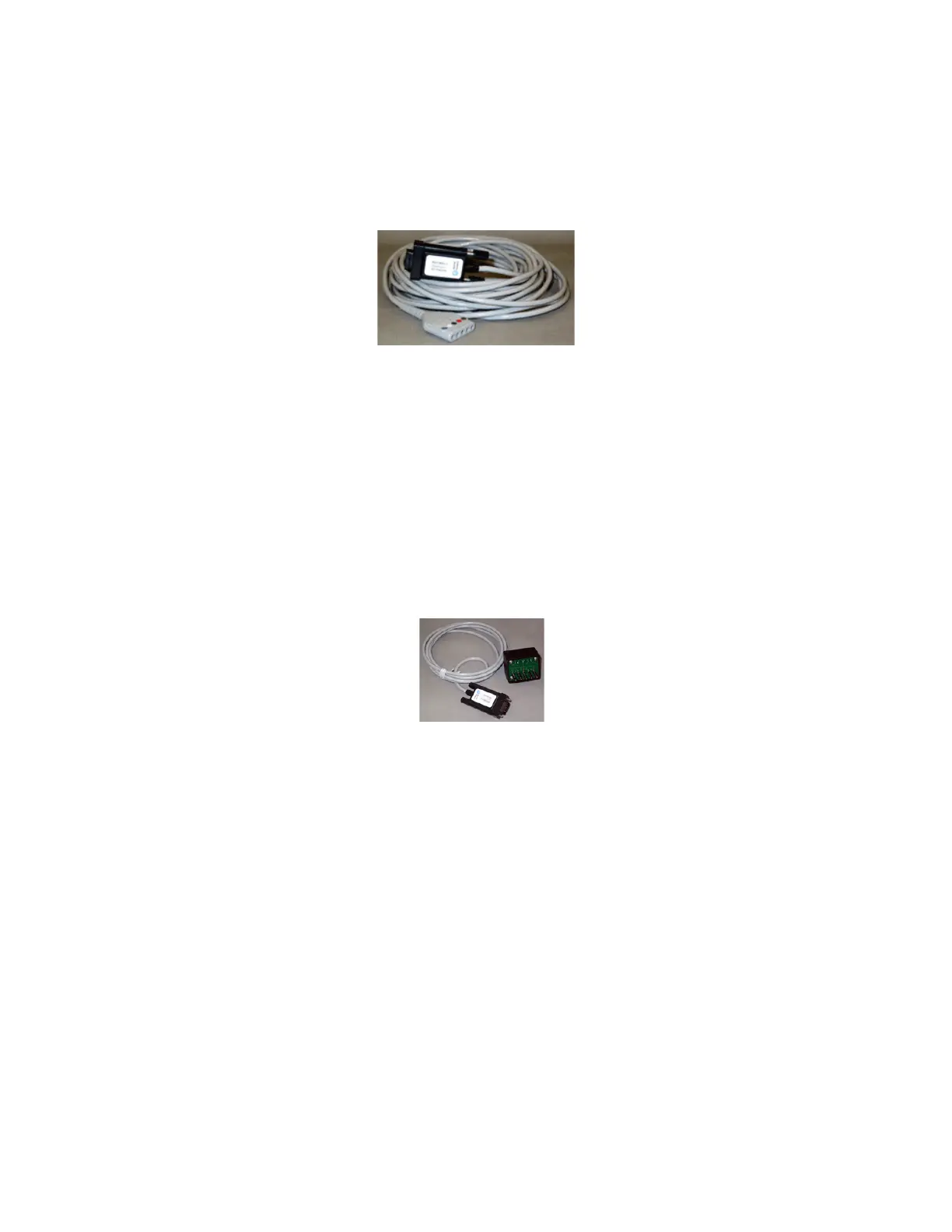
Transducer Cable – Biopac to RF panel
This is a transducer cable suitable to use inside the MRI control room (see figure 4). It supports one to
five subject electrical connections and is 2 meters long. The cable incorporates a plastic housed DSUB9
Male connector to panel mount with the control room exposed DSUB9 female connector of the MRI
filter. This cable connects directly to any of the following transducer amplifiers: ECG100C-MRI,
EDA100C, RSP100C-MRI.
Figure 4. Transducer Cable in control room
Preparing for an experiment:
1. Open the BIOPAC MP150 unit
The power button is on the front panel of the device. Note: it will take about a minute for the
computer to recognize that the device is on.
2. Open Acknowledge software in Backup-PC
Once the MP150 unit is on a message will be shown on the desktop of the Backup-PC. Click on the
“Template.acq” file at C:/Biopac data-Main Template to open the software. Note: You can also open
any Acknowledge file or create a new one of your own. "Template.acq" has all the required channels
 Loading...