10 KB-520-6
Verdichter und Motor auf Grund -
rahmen ausrichten
• Diese Ausführung erfordert einen
stabilen Grundrahmen mit solider
Auflage und Befestigung auf dem
Fundament.
• Motor- und Verdichterwelle müssen
exakt aufeinander ausgerichtet
sein. Für den Höhenausgleich eig-
nen sich nur stabile Unterlagen
(z. B. Stahlklötze, Bleche).
• Zulässige Abweichungen von
BITZER-Kupplungen bei Mitten -
versatz und Luftspalt zwischen den
Kupplungs hälften (min. 4 Mess-
Positionen am Scheibenumfang):
Mittenversatz..........max. 0,15 mm
Luftspalt..................max. 0,25 mm
Achtung!
Schlecht ausgerichtete Kupplun -
gen bewirken vorzeitigen Ausfall
der Kupplung sowie Schäden an
Lagern und Wellenabdichtung.
Motorwelle und Verdichterwelle
sehr sorgfältig ausrichten!
Achtung!
Die Befestigungselemente der
beiden Kupplungsteile müssen
fest angezogen werden, damit
sie sich im Betrieb nicht lockern!
Aligning compressor and motor on
base frame
• This design requires a solid base
frame with strong supporting sur -
faces well fixed to the foundation.
• The motor and compressor must
be exactly aligned with respect to
each other. Only rigid elements are
suitable for height compensation
(e.g. steel blocks, shims).
• Permissible deviation of BITZER
couplings, with displacement on the
axis and variations in the air gap
between the coupling halves (mea -
sured at a minimum of 4 points on
the outer circumference):
Axis displacement....max. 0.15 mm
Air gap....................max. 0.25 mm
Attention!
Faulty alignement causes pre -
mature failure of the coupling
and damage to bearings and the
shaft seal.
Align motor shaft and com -
pressor shaft very carefully!
Attention!
The fixing elements of both the
coupling halves must be firmly
tightened to prevent loosening
during operation!
Aligner compresseur et moteur sur
cadre de base
• Ce type de mon tage exige un cadre de
base sta ble avec un appui et une fixa -
tion soli des sur la semel le.
• Les arbres du moteur et du com pres -
seur doi vent être rigou reu se ment ali -
gnés. N'utiliser que des cales sta bles
(par ex. plots en acier, tôles) pour com -
pen ser les dif fé ren ces de niveau.
• Différences admis si bles pour les
accou ple ments BITZER en cas de
déport cen tral et jeu admis si ble entre
les deux moi tiés d'accouplement (au
mini mum 4 points de mesu re sur le
pour tour du dis que):
Déport cen tral ........max. 0,15 mm
Jeu ........................max. 0,25 mm
Attention !
Un ali gne ment impar fait pro vo que
une dété rio ra tion pré ma tu rée de
l'accouplement ainsi que des dé -
fauts aux paliers et à la gar ni ture
d'étan ché ité.
Veuillez aligner soigneusement les
arbres du moteur et du compres -
seur !
Attention !
Les élé ments de fixa tion des deux
paliers d'accouplement doi vent être
ser rés fer me ment afin d'éviter tout
des ser ra ge durant le fonc tion ne ment !
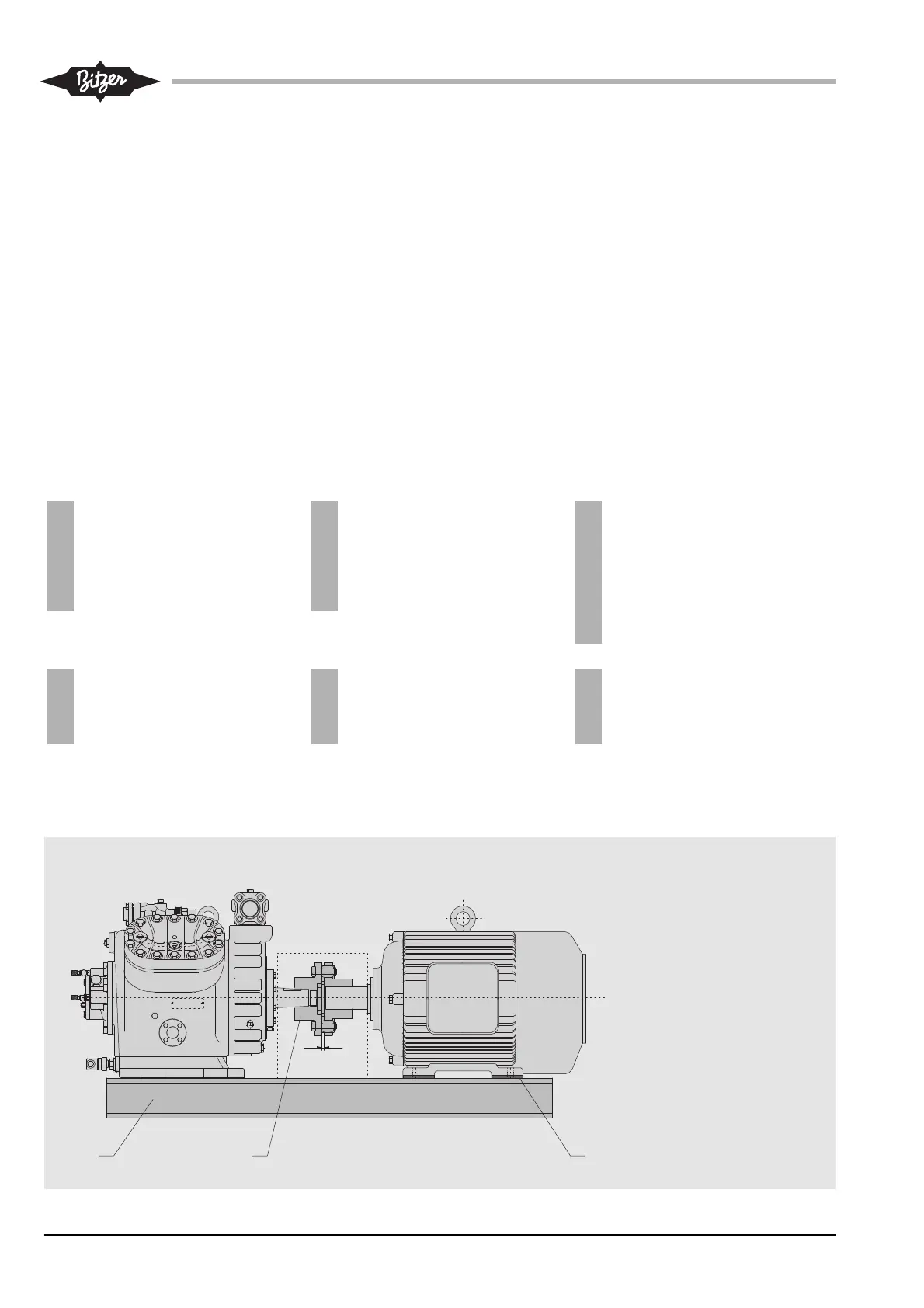
Abb. 7 Motor-Verdichter-Satz
auf Grundrahmen
Fig. 7 Motor-compressor set
on base frame
Fig. 7 Unité moteur-compresseur sur cadre
de base
1 Stabiler Grundrahmen
Sturdy base frame
Chasis commun stable
2 Kupplung
Coupling
Accouplement
3 Unterlagen (bei Bedarf)
Shims (if required)
Cales d’épaisseur (si nécessaire)