18 KB-570-1 RUS
ST-130-2
2
2 Functions
The OLC-D1-S can monitor either the
minimum or the maximum oil level,
depending on its mounting position
and incorporation into the safety
chain. If the minimum and the maxi-
mum oil level should be monitored,
two OLC-D1-S devices must be
installed.
2.1 Monitoring of the minimum
level
Lock out
The compressor is shut off, if the
prism sticks out of the oil longer than
the delay time specified by the circuit.
The OLC-D1-S then opens the output
contact and the circuit locks out elec-
tronically: The control voltage to the
compressor contactor is interrupted.
The red LED at the face side of the
opto-electronic unit lights up (figure 1)
as well as the signal lamp H4.
Reset
The circuit can be manually reset by
pressing the reset button. This reset
button (S4) has to be mounted into
the swich board. (Connection see
sche matic wiring diagram.)
2 Fonctionnement
Le OLC-D1-S peut contrôler soit le
niveau d'huile minimal soit le niveau
d'huile maximal, dépendant de la position
de montage et de l'intégration dans la
chaîne de sécurité. Pour surveiller le
niveau d'huile minimal et maximal en
même temps, deux OLC-D1-S doivent
être installés.
2.1 Contrôle du niveau d'huile minimal
Verrouiller
Le compresseur est arrêté des lors que le
temps pendant lequel le cône de verre
dépasse le niveau d'huile est supérieur à
la la temporisation prédéfinie par le
réglage.
Le OLC-D1-S ouvre alors le contact de
sortie et le circuit se verrouille électroni-
quement: la tension de commande du
con tacteur du compresseur est alors
coupée. La LED rouge sur le côté frontal
de l'unité opto-électronique s'allume (figu-
re 1) et ainsi que la lampe H4.
Déverrouiller
Le circuit peut être remis manuellement
en fonctionnement par la touche de reset.
Cette touche (S4) devra être montée
dans l'armoire électrique. (Raccordement
voir schéma de principe.)
2 Funktionen
Das OLC-D1-S kann entweder das
mini male oder das maximale Ölnive au
über wachen, je nach Montage-Posi ti -
on und Einbettung in die Sicher heits -
kette. Falls sowohl das mini male wie
das maximale Ölnive au über wacht
werden soll, müssen zwei OLC-D1-S
installiert werden.
2.1 Minimale Ölniveau-Überwa-
chung
Verriegeln
Der Verdichter wird abgeschaltet,
wenn der Glas-Kegel länger als die
durch die Schaltung vorgegebene Ver -
zöge rungs zeit aus dem Öl herausragt.
Das OLC-D1-S öffnet dann den Aus -
gangs kon takt und die Schaltung ver-
riegelt elektronisch: Die Steuerspan -
nung zum Verdich ter schütz wird unter-
brochen. Die rote LED auf der Stirn -
seite der opto-elektronischen Ein heit
(Abb. 1) und die Signallampe H4
leuchten.
Entriegeln
Die Schaltung kann über eine Reset-
Taste manuell zurück gesetzt werden.
Diese Reset-Taste (S4) muss im
Schalt schrank montiert werden.
(Anschluss siehe Prinzipschaltbild.)
Abb. 1 Abmessungen und Aufbau Fig. 1 Dimensions and design
Fig. 1 Dimensions et construction
1 Prisma-Einheit
2 Glas-Kegel
3 Dichtung
4 Opto-elektronische Einheit "OLC-D1"
(360° drehbar)
5 Anschlusskabel
6 Schraubkappe
1 Prism unit
2 Glass cone
3 Gasket
4 Opto-electronic unit "OLC-D1"
(360° revolving)
5 Connecting cable
6 Screwing cap
1 Unité prisme
2 Cône en verre
3 Joint
4 Composant opto-électronique "OLC-D1"
(mobile sur 360°)
5 Câble de raccordement
6 Chapeau à visser
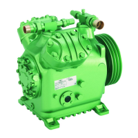
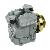
6.2 Elektromagnet-Kupplung
ausbauen
Achtung!
Verdichterschaden möglich! Beim
Ausbau der Kupplung darf die
Welle keinesfalls durch Hebeln
zur Antriebsseite hin verschoben
werden!
Kupplung genau nach Anleitung
des Herstellers ausbauen.
Ausbau-Beispiel für LINNIG Kupplung
LA18.060Y (siehe auch Abb. 4):
• Stromversorgungunterbrechenund
Verdichter auf mindestens 40°C
abkühlen lassen.
• ZentraleSchraubeM10heraus-
schrauben. Ankerscheibe von der
Verdichterwelle ziehen.
• EinstellscheibenfürWiedermontage
aufbewahren. Sicherungsring vor
dem Lager entfernen.
• Riemenscheibeherunterziehen.Die
4 Schrauben M6, mit denen der
Magnet befestigt ist, herausschrau-
ben und Magnet abziehen.
6.3 Wellenabdichtung
Eine routinemäßige Überprüfung der
Wellenabdichtung ist im Regelfall nicht
erforderlich.
Die Wellenabdichtung arbeitet mit
einer Ölvorlage, die ein Austreten von
Kältemittel verhindert. Das Öl bildet
einen dünnen Schmier- und Dichtfilm
und trägt zusätzlich zur Kühlung der
Wellenabdichtung bei.
Leckölmengen bis ca. 0,05 cm
3
pro
Betriebsstunde liegen im zulässigen
Toleranzbereich. Austretendes Öl wird
im Ölsammelraum aufgefangen.
Viermal jährlich und bei Ölaustritt and
der Welle Ölstand im Verdichter prüfen
und ggf. Öl ergänzen. Wenn Öl nach-
gefüllt werden muss, Ölsammelraum
über Service-Anschluss (Seiten 12, 13,
Pos. 10) entleeren.
6.2 Removingtheelectro-magnetic
clutch
Attention!
Compressor damage possible!
The shaft must never be forced
towards the drive side by the use
of levers to remove the clutch!
By removing the electro-magnetic
clutch keep exactly to the
instructions of the manufacturer.
Removal example for LINNIG clutch
LA18.060Y (see also fig. 4):
• De-energizecompressorandhave
it cooled down to at least 40°C.
• Unscrewandremovecentralscrew
M10. Pull armature disc from
compressor shaft.
• Keepadjustingwashersforre-
assembly. Remove retaining ring
before bearing.
• Removepulley.Unscrewandre-
move the 4 screws M6 which are
used to fix the magnet and pull off
magnet.
6.3 Shaftseal
It is not necessary to make a regulary
routine inspection of the shaft seal.
The shaft seal works with an oil
barrier, which prevents leakage of
the refrigerant. The oil forms a thin
lubricant and sealing film and also
contributes to cooling the shaft seal.
Leakage oil quantities up to 0.05 cm
3
per hour are within the permitted
tolerance range.
Four times a year and in case of oil
loss at the shaft check oil level in
compressor and add oil if necessary.
If oil is added, drain oil reservoir via
service connection (pages 12, 13,
pos. 10).
6.2 Снятие электромагнитной
муфты
Внимание!
Возможно повреждение
компрессора!
При демонтаже муфты, не
перемещать вал в сторону привода
при помощи рычагов!
Демонтаж электромагнитной муфты
производить в соответствии с
инструкциями производителя.
Пример демонтажа муфты Linnig
LA18.060Y (см. также рис 4.):
• Обесточьте компрессор и дайте ему
остыть до менее 40°C.
• Отверните и снимите центральный
болт М10. Вытяните анкерный диск
с вала компрессора.
• Сохраните регулировочные шайбы для
повторной сборки. Снимите стопорное
кольцо перед подшипником.
• Снимите шкив. Отверните 4 винта M6
используемые для крепления магнита
и снимите магнит.
6.3 Сальник
Нет необходимости выполнять
регулярную проверку сальника.
Сальник работает с масляным барьером,
который препятствует утечке хладагента.
Масло образует тонкий слой смазочного
материала и герметизирующую пленку,
а также способствует охлаждению
сальника.
Утечка масла в объеме до 0,05 см
3
в
час находится в пределах допустимого
диапазона.
Четыре раза в год и в случае утечки
масла по валу проверяйте уровень
масла в компрессоре и добавляйте при
необходимости. Если масло добавлено,
слить масло из резервуара через
сервисное присоединение (стр. 12, 13,
поз. 10).
 Loading...