ADD:
The inputs from channel 1 and channel 2 are
summed and displayed as a single signal. If the
Channel 2 POSition/PULL INVert control is
pulled out, the input from channel 2 is subtracted
from channel 1 and the difference is displayed as a
single signal.
13. CH1 AC-GND-DC Switch. Three-position lever
switch with the following positions:
AC:
Channel 1 input signal is capacitively coupled; dc
component is blocked.
GND:
Opens signal path and grounds input to vertical
amplifier. This provides a zero-volt base line, the
position of which can be used as a reference when
performing dc measurements.
DC:
Direct coupling of channel 1 input signal; both ac
and dc components of signal produce vertical de-
flection.
14. CH1 (X) Input Jack. Vertical input for channel 1.
X-axis input for X-Y operation.
15. CH1 (X) VOLTS/DIV Control. Vertical attenuator
for channel 1. Provides step adjustment of vertical
sensitivity. When channel 1 VARiable control is set
to CAL, vertical sensitivity is calibrated in 10 steps
from 5 mV/div to 5 V/div in a 1-2-5 sequence. When
the X-Y mode of operation is selected, this control
provides step adjustment of X-axis sensitivity.
16. CH1 VARiable/PULL X5 MAG Control:
VARiable:
Rotation provides vernier adjustment of channel 1
vertical sensitivity. In the fully-clockwise (CAL)
position, the vertical attenuator is calibrated. Coun-
terclockwise rotation decreases gain sensitivity. In
X-Y operation, this control becomes the vernier
X-axis sensitivity control.
PULL X5 MAG:
When pulled out, increases vertical sensitivity by a
factor of five. Effectively provides two extra sensi-
tivity settings: 2 mV/div and 1 mV/div. In X-Y
mode, increases X-sensitivity by a factor of five.
17. CH1 POSition/PULL ALT TRIGger Control:
POSition:
Adjusts vertical position of channel 1 trace.
PULL ALT:
Used in conjunction with the Trigger SOURCE
switch to activate alternate triggering. See the de-
scription under the Trigger SOURCE switch.
18. CH2 POSition/PULL INVert Control:
POSition:
Adjusts vertical position of channel 2 trace. In X-Y
operation, rotation adjusts vertical position of X-Y
display.
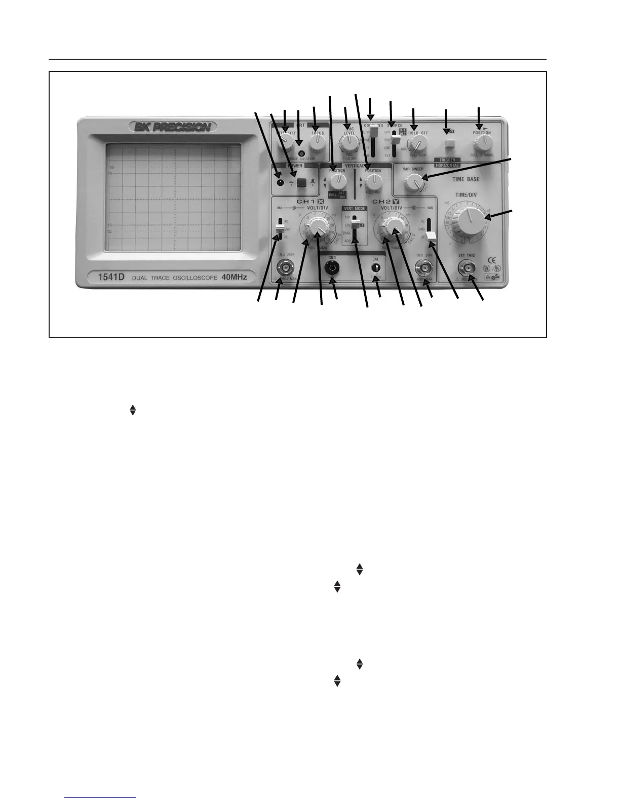
CONTROLS AND INDICATORS
Fig. 2. Model 1541D Controls and Indicators.
8
3
6
1
4
17
33
18
32
31
30
28
27
26
33
34
22
21
20
19
10
12
9
16
15
14
13
5