EasyManua.ls Logo

BK Precision 8600 User Manual

BK Precision 8600
107 pages
To Next Page IconTo Next Page
Page #1 background imageLoading...
Page #1 background image
Model: 8600, 8601, 8602, 8610, 8612, 8614, 8616, 8620, 8622,
8624, and 8625
Programmable DC Electronic Loads
USER MANUAL

Table of Contents

Question and Answer IconNeed help?

Do you have a question about the BK Precision 8600 and is the answer not in the manual?

BK Precision 8600 Specifications

General IconGeneral
BrandBK Precision
Model8600
CategoryTest Equipment
LanguageEnglish

Summary

Safety Summary

Category rating

Defines safety category ratings for electrical energy and voltage impulses.

Electrical Power

Ground the Instrument

Do not operate in an explosive or flammable atmosphere

Do not operate instrument if damaged

Clean the instrument only as instructed

Not for critical applications

Do not touch live circuits

Fuse replacement

Servicing

Cooling fans

Do not short-circuit batteries

Use correctly sized wires

Compliance Statements

CE Declaration of Conformity

Safety Symbols

1 General Information

1.1 Product Overview

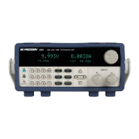
Describes the 8600 Series DC Electronic Loads and their applications.

1.2 Package Contents

Lists items included in the instrument's shipping carton.

1.3 Product Dimensions

Shows physical dimensions and rackmount compatibility.

1.4 Rackmount Installation

Instructions for installing the instrument in a standard 19-inch rack.

1.5 Front Panel Overview

Identifies and labels controls and indicators on the front panel.

1.6 Rear Panel Overview

Identifies and labels connectors and ports on the rear panel.

1.7 Display Overview

Explains the different parts and indicators on the instrument's display.

Front Panel Description

Rear Panel Description

Display Description

2 Getting Started

2.1 Input Power and Fuse Requirements

Details AC input voltage, frequency, and fuse specifications.

Fuse Requirements

Fuse Replacement

2.2 Input Connections

2.3 Preliminary Check

Verify AC Input Voltage

Steps to verify the correct AC input voltage is available.

Connect Power and Self Test

Procedure to connect power and initiate the instrument's self-test.

Self-test Errors

Input Check

Check Model and Firmware Version

3 Front Panel Operation

3.1 Menu Options

Overview of the System and Config menus for instrument settings.

System Menu

Lists options available within the System menu.

Config Menu

Lists options available within the Config menu.

How to Navigate the Menu

3.2 Configure Operation Modes (CC/CV/CR/CW)

Constant Current (CC) Mode

Explains CC mode and how to configure its parameters.

Configure CC Parameters

Details parameters like Range, High/Low limits, and Rise/Fall time.

CC Mode Parameters

Slew Rate Measurement and Actual Transition time

Constant Voltage (CV) Mode

Configure CV Parameters

Details parameters like Range, High/Low current limits.

CR Mode Parameters

Constant Power (CW) Mode

Configure CW Parameters

Setting CC, CV, CR, CW Mode

3.3 SYSTEM Menu

Restore Factory Default Settings

Configure Power-On State

Load On Knob

Configure Trigger Source

Save/Recall Instrument Settings

Select Storage Group

Save Settings

Recall Settings

Display Input On Timer

Remote Interface Setup

RS-232

USBTMC

GPIB

3.4 CONFIG Menu

Von Operation

How to set the voltage turn-on state and its latch behavior.

Configure Protection Settings

Overcurrent Protection (OCP)

Explanation of hardware and software OCP features and configuration.

Software OCP

Operations to Clear the OCP State

Overpower Protection (OPP)

Software OPP

Operations to Clear the OPP State

Overvoltage Protection (OVP)

Overtemperature Protection (OTP)

Reverse Voltage Protection (LRV/RRV)

Configure Timed Input

Measurement Configurations

Voltage Auto Range

How to enable or disable voltage auto range.

Measuring Rise and Fall Time

Measurement Averaging Filter

CR LED Function

Remote Sense

External Analog Control and Monitor

External Current Control

How to control current using external analog programming terminals.

External Input On/Off Control

Voltage Fault Indicator

Current Monitor

3.5 Short Operation

3.6 Transient Operation

Continuous

Generates a pulse stream toggling between two load levels.

Pulse

Generates a transient pulse of programmable width.

Toggle

Switches between two levels upon receiving a trigger.

3.7 List Operation

Run List

3.8 Battery Test Function

Stop Voltage

Sets the cut-off voltage level for the battery test to end.

Stop Capacity

Sets the capacity level for the battery test to end.

Stop Timer

Sets a timer for the battery test to end.

3.9 Test Operations

Automatic Test Function

How to simulate various tests, edit program files, and set Pass/Fail criteria.

OCP Test Function

OPP Test Function

3.10 Key Lock

4 Remote Operation

4.1 Interface Connection

Details on connecting via RS-232, GPIB, and USBTMC interfaces.

RS-232

RS-232 pinout information and cable requirements.

USBTMC

GPIB

4.2 Remote Commands

5 Troubleshooting Guide

General

FAQs and solutions for general operational issues like powering up.

Remote Control

Troubleshooting steps for remote communication issues.

6 Specifications

Input Ratings

Voltage, current, and power ratings for different models.

CV Mode

Specifications for Constant Voltage mode operation.

CC Mode

Specifications for Constant Current mode operation.

CR Mode

Specifications for Constant Resistance mode operation.

CW Mode

Specifications for Constant Power mode operation.

Transient Mode (CC mode)

Measurement

Protection Range (typical)

General (typical)

Supplementary Characteristics

Memory capacity

Recommended calibration period

AC Input (selectable by switch on the rear panel)

Cooling method

Environmental conditions

7 Calibration

Index

SERVICE INFORMATION

LIMITED THREE-YEAR WARRANTY

Related product manuals