9
when an event such as a current protection occurs. When the interrupt occurs, your program can then
act on the event in the appropriate fashion.
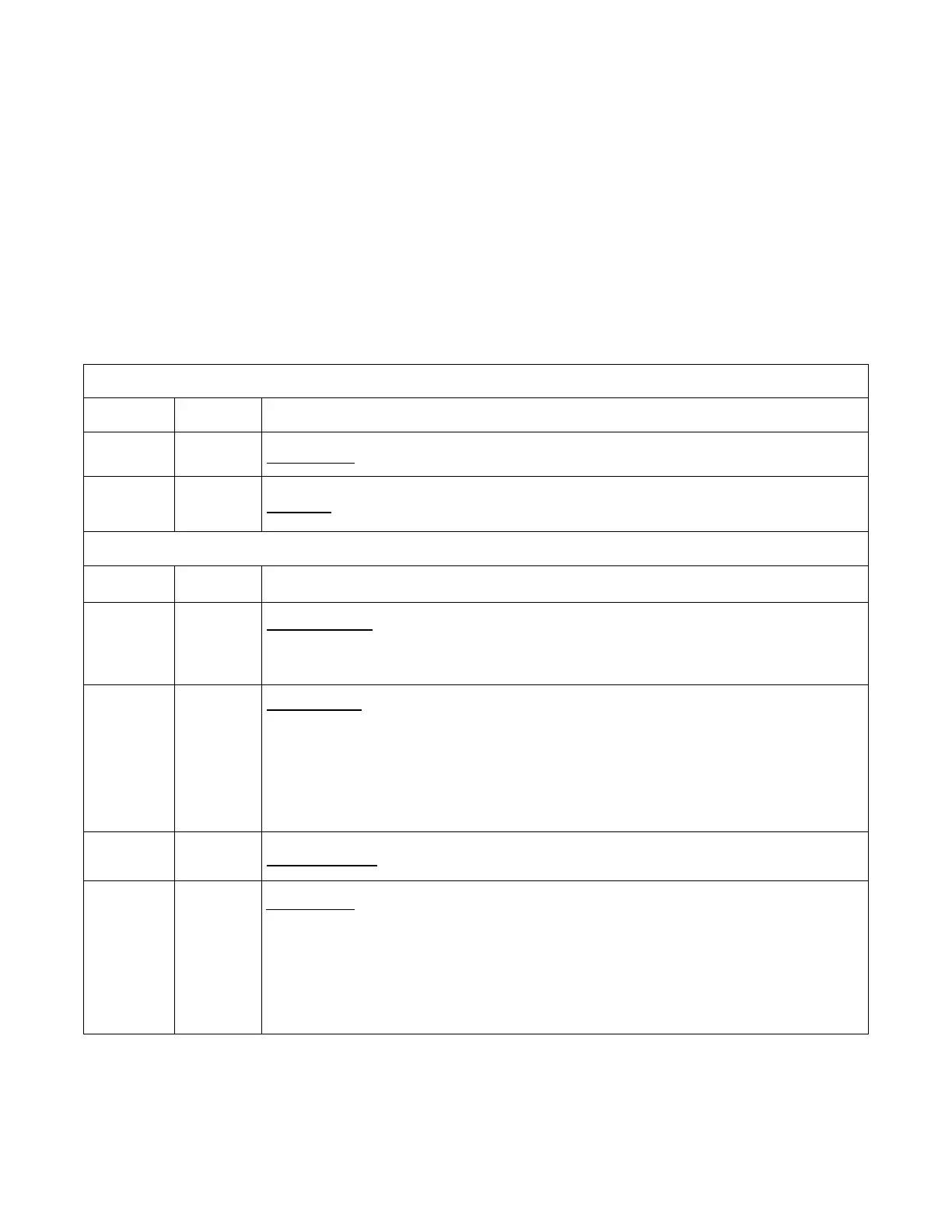
The following table defines the status bits. Figure shows the status register structure of the electronic
load. The Standard Event, Status Byte, and Service Request Enable registers and the Output Queue
perform standard GPIB functions as defined in the IEEE 488.2 Standard Digital Interface for
Programmable Instrumentation. The Operation Status and Questionable Status registers implement
functions that are specific to the electronic load.
Bit Configurations of Status Registers
Operation Status Group
Bit Signal Meaning
0 CAL Calibrating. The electronic load is computing new calibration constants.
5 TRG Waiting. The electronic load is waiting for a trigger.
Status Group
Bit Signal Meaning
0 VF
Voltage Fault. Either an overvoltage or a reverse voltage has occurred. This bit
reflects the active state of the FLT pin on the back of the unit. The bit remains
set until the condition is removed and PROT:CLE is programmed.
1 OC
Overcurrent. An overcurrent condition has occurred. This occurs if the current
exceeds 102% of the rated current or if it exceeds the user-programmed
current protection level. Removing the overcurrent condition clears the bit. If
the condition persists beyond the user programmable delay time, PS bit is also
set and the input is turned off. Both bits remain set until the condition is
removed and PROT:CLE is programmed.
2 RS Remote Sense. When the remote sense is connected, this bit is set.
3 OP
Overpower. An overpower condition has occurred. This occurs if the unit
exceeds the max power or it exceeds the user-programmed power protection
level. Removing the overpower condition clears the bit. If the condition
persists beyond the user programmable delay time, PS bit is also set and the
input is turned off. Both bits remain set until the condition is removed and
PROT:CLE is programmed.