Do you have a question about the Black & Decker BDXCTSH1 and is the answer not in the manual?
Explains safety alert symbols used in the manual for hazards and risks.
Lists the included components and accessories for the thermostat installation.
Crucial step to ensure safety by turning off the HVAC system power before installation.
Guides on referencing wiring configurations and recording existing wire colors and functions.
Instructions for safely removing the old thermostat and securing wires to prevent loss.
Steps for attaching the mounting plate and optional wall plate to the wall.
Details the process of inserting wires into the thermostat's terminal sockets securely.
Describes how to connect the thermostat display unit to the installed mounting plate.
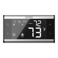
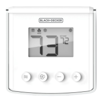
Identifies and explains the function of each key on the BDXCTSH1 Smart Thermostat.
Explains advanced key combinations for features like mode switching and keypad locking.
Details how to navigate and select thermostat parameters using the device keys.
Explains how the thermostat displays the set point temperature and the current room temperature.
Lists configuration options for various HVAC system types like Conventional and Heat Pump.
Covers settings for fan type, heat pump valve defaults, temperature units, and clock format.
Settings for frost protection, temperature calibration, backlight behavior, and auto recovery.
Parameters for thermostat response time, and temperature differentials.
Settings for filter replacement warnings and device reset functions.
Illustrates the sequence of operating modes for different HVAC system types.
Table showing which operating modes are available based on the HVAC system configuration.
Wiring diagram for conventional furnace/AC systems with one transformer.
Wiring diagram for conventional boiler/AC systems with two transformers.
Wiring diagram for heat pump systems with one transformer.
Wiring diagram for fan coil units with 4-pipe configuration.
Wiring diagram for fan coil units with 2-pipe configuration.
States compliance with FCC rules and conditions for device operation.
Covers RF radiation exposure limits and compliance with Industry Canada standards.
| Brand | Black & Decker |
|---|---|
| Model | BDXCTSH1 |
| Category | Thermostat |
| Language | English |