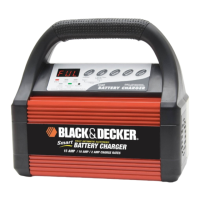
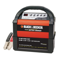
I N T R O D U C T I O N
Thank
you
for selecting
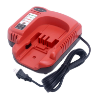
the Black & Decker 6 Amp / 4 Amp / 2 Amp Smart Battery Charger.
With proper
care and
use, it will give you years
of dependable
service. This
battery
charger
has
a
high
charge
rate of up
to
6
amps, and low charge rate
of 2 amps. It
is
designed
for
charging
only 12-volt lead-acid batteries — conventional automotive, maintenance-free,
marine deep
cycle
and gel — used
in
cars, farm equipment,
boats, RVs
and SUVs, lawn
mowers/garden
tractors, motorcycles, personal watercraft, snowmobiles, ATVs
and various
a p p l i c a t i o n s .
Smart Battery
Chargers feature 3-stage, high-efficiency charging technology, built-in
microprocessor control that ensures fast, safe and
complete
charging
of serviceable
b a t t e r i e s .
C h a rge Curv e
Stage One — Rapid Start
Charge at
6 amps delivers
maximum charging amperage
to “wake up” any
serviceable 12 volt
battery and allows for
quick
engine starting in
just
8 minutes (based on
a midsize vehicle batt
ery
at
50% charge
level). When
battery reaches a maximum safe predetermined voltage, the charger will
automatically
signal a "beep"
and move into Stage 2 of
the
charging process.
Stage
Two — Absorption Charge maintains
the maximum
possible charge at
a
constant,
safe,
predetermined voltage.
During the phase,
voltage absorption
regulation charge, the
charging
voltage
remains
constant,
while
the actual
charging
BEEP
BEEP
OFF BEEP
STAGE THREE
CHARGING
COMPLETE
STAGE ONE
STAGE TWO
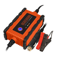
4 . Determine which post of battery is grounded (connected) to the chassis. If negative post
is grounded to chassis (as in most vehicles), see 5. If positive post is grounded to the
chassis, see 6.
5. For negative-grounded vehicle, connect POSITIVE (RED) clamp from battery charger
to POSITIVE (POS, P, +) ungrounded post of battery. Connect NEGATIVE (BLACK)
clamp to vehicle chassis or engine block away from battery. Do not connect clip to
carburetor, fuel lines, or sheet-metal body parts. Connect to heavy gauge metal part of
the frame or engine block.
6. For positive-grounded vehicle, connect NEGATIVE (BLACK) clamp from battery
charger to NEGATIVE (NEG, N, –) ungrounded post of battery. Connect POSITIVE
(RED) clamp to vehicle chassis or engine block away from battery. Do not connect clip
to carburetor, fuel lines or sheet-metal body parts. Connect to a heavy gauge metal
part of the frame or engine block.
7. When disconnecting charger, disconnect AC cord, remove clamp from vehicle chassis,
and then remove clamp from battery terminal.
8. Do not charge the battery while the engine is operating.
9. See operating instructions for length of charge information.
Follow these steps when the battery has been removed from a vehicle. A spark near
the battery may cause an explosion. To reduce risk of a spark near the battery:
1. Check polarity of battery posts. POSITIVE post (marked POS,P, +) usually has a larger
diameter than the NEGATIVE battery post (marked NEG, N, –).
2. Attach a 24-inch (minimum length) 6 AWG insulated battery cable to the NEGATIVE
battery post (marked NEG, N, –).
3. Connect the POSITIVE (RED) battery clamp to the POSITIVE battery post (marked
POS, P, + or red).
4. Stand as far back from the battery as possible, and do not face battery when making
final connection.
5. Carefully connect the NEGATIVE (BLACK) charger clamp to the free end of the battery
cable connected to the NEGATIVE terminal.
6. Set the charge rate to appropriate setting according to battery size.
7. When disconnecting charger, always do so in reverse sequence of connecting
procedure and break first connection while as far away from battery as practical.
Note: A marine (boat) battery must be removed and charged on shore. To charge it
on board requires equipment specially designed for marine
use. This unit is
NOT designed for such use.
SAVE THESE INSTRUCTIONS
This device complies with part 15 of the FCC rules. Operation is subject to the following two conditions:
(1) this device may not cause harmful interference, and (2) this device must accept any interference
received, including interference that may cause undesired operation.
This equipment has been tested and found to comply with the limits for a Class B digital device, pursuant
to part 15 of the FCC Rules. These limits are designed to provide reasonable protection against harmful
interference in a residential installation. This equipment generates, uses and can radiate radio frequency
energy and, if not installed and used in accordance with the instructions, may cause harmful interference
to radio commu
nications. However, there is no guarantee that interference will not occur in a particular
installation. If equipment does cause harmful interference to radio or television reception, which can be
determined by turning the equipment off and on, the user is encouraged to try to correct the interference
by one or more of the following measures:
• Reorient or relocate the receiving antenna.
• Increase the separation between equipment and receiver.
• Connect the equipment into an outlet on a circuit different from that to which the receiver is
connected.
• Consult the dealer or an experienced radio/TV technician for help.
Modifications not authorized by the manufacturer void user’s authority to operate this device.
 Loading...